
Page 44 - Dynamic Vision for Perception and Control of Motion
P. 44
28 2 Basic Relations: Image Sequences – “the World”
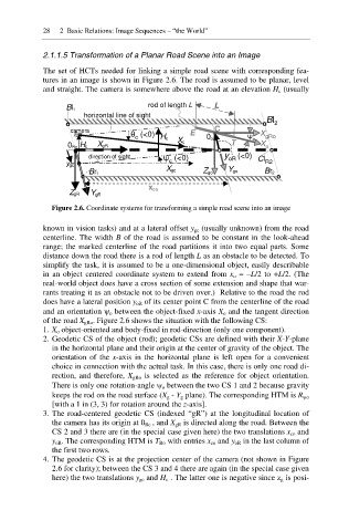
2.1.1.5 Transformation of a Planar Road Scene into an Image
The set of HCTs needed for linking a simple road scene with corresponding fea-
tures in an image is shown in Figure 2.6. The road is assumed to be planar, level
and straight. The camera is somewhere above the road at an elevation H c (usually
rod of length L L
Bl 1
horizontal line of sight
o o Bl 2
camera C
ș (<0) H c E o ȥ X gRo
c
X c 0 o T o X
0 Rc H c X gR o
o o o
direction of sight ȥ (<0) y oR (<0) Cl
y gc o c R2
X gc Y go
Br 1 Z go Br 2
o o
x co
Z gR Y gR
Figure 2.6. Coordinate systems for transforming a simple road scene into an image
known in vision tasks) and at a lateral offset y gc (usually unknown) from the road
centerline. The width B of the road is assumed to be constant in the look-ahead
range; the marked centerline of the road partitions it into two equal parts. Some
distance down the road there is a rod of length L as an obstacle to be detected. To
simplify the task, it is assumed to be a one-dimensional object, easily describable
in an object centered coordinate system to extend from x o = –L/2 to +L/2. (The
real-world object does have a cross section of some extension and shape that war-
rants treating it as an obstacle not to be driven over.) Relative to the road the rod
does have a lateral position y oR of its center point C from the centerline of the road
and an orientation \ o between the object-fixed x-axis X o and the tangent direction
of the road X gRo. Figure 2.6 shows the situation with the following CS:
1. X o object-oriented and body-fixed in rod-direction (only one component).
2. Geodetic CS of the object (rod); geodetic CSs are defined with their X-Y-plane
in the horizontal plane and their origin at the center of gravity of the object. The
orientation of the x-axis in the horizontal plane is left open for a convenient
choice in connection with the actual task. In this case, there is only one road di-
rection, and therefore, X gRo is selected as the reference for object orientation.
There is only one rotation-angle \ o between the two CS 1 and 2 because gravity
keeps the rod on the road surface (X g - Y g plane). The corresponding HTM is R \o
[with a 1 in (3, 3) for rotation around the z-axis].
3. The road-centered geodetic CS (indexed “gR”) at the longitudinal location of
the camera has its origin at 0 Rc , and X gR is directed along the road. Between the
CS 2 and 3 there are (in the special case given here) the two translations x co and
y oR. The corresponding HTM is T Ro with entries x co and y oR in the last column of
the first two rows.
4. The geodetic CS is at the projection center of the camera (not shown in Figure
2.6 for clarity); between the CS 3 and 4 there are again (in the special case given
here) the two translations y gc and H c . The latter one is negative since z g is posi-