
Page 42 - Dynamic Vision for Perception and Control of Motion
P. 42
26 2 Basic Relations: Image Sequences – “the World”
x x O angle for cameras); the rota-
tion takes place around an in-
T termediate y-axis, called node
axis k y . This already yields the
x o P new x-direction x O, around
-z 0 \
which the final rotation takes
y o place: The roll– or bank angle
I indicates the angle around
I I this axis between the plane of
T symmetry of the vehicle and
the vertical plane. All of these
z y z O y O angles are shown twice in the
figure for easier identification
Figure 2.3. Transformation of a coordinate system of the individual axis of rota-
tion.
2.1.1.3 Scaling
Due to Equation 2.1 scaling can be achieved simply by setting the last element in
the HTM [lower right element p (4, 4)] different from 1. All components are then
interpreted as scaled by the same factor p. This scaling is conveniently exploited by
application to perspective mapping.
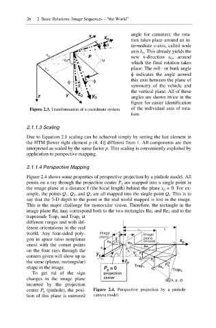
2.1.1.4 Perspective Mapping
Figure 2.4 shows some properties of perspective projection by a pinhole model. All
points on a ray through the projection center P p are mapped into a single point in
the image plane at a distance f (the focal length) behind the plane x p = 0. For ex-
ample, the points Q 1, Q 2, and Q 3 are all mapped into the single point Q i. This is to
say that the 3-D depth to the point in the real world mapped is lost in the image.
This is the major challenge for monocular vision. Therefore, the rectangle in the
image plane Re i may correspond both to the two rectangles Re 1 and Re 2 and to the
trapezoids Trap 1 and Trap 2 at
different ranges and with dif-
ferent orientations in the real
x 1 x 2
world. Any four-sided poly- Image Image
plane f f
gon in space (also nonplanar Q i plane x
Re i (mirrored) x 1 x 2 p
ones) with the corner points Re i
Re 1
-y i
on the four rays through the y i O
corners given will show up as y p -z i z i P 1 O
y 2 Q 1 P 2
the same (planar, rectangular) z p O
P 3
shape in the image. P =0 Trap 1 Q 2 Re 2 Trap 2
p
To get rid of the sign projection
changes in the image plane center Q 3 (x, y, z)
O
incurred by the projection
center P p (pinhole), the posi- Figure 2.4. Perspective projection by a pinhole
tion of this plane is mirrored camera model