
Page 43 - Dynamic Vision for Perception and Control of Motion
P. 43
2.1 Three-dimensional (3-D) Space and Time 27
at x p = 0 (as shown). This allows us to easily write down the mathematical relation-
ship of perspective mapping when the x p-axis is selected perpendicularly to the im-
age plane and the origin is at the pin hole (projection center):
f
y
y i / /
x
/ / ,
f
z
z
x
i
(2.4)
y / ( (1 / ))
y
x
f
or i
z i / ( (1 / )).
x
f
z
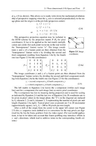
This perspective projection equation may be included in
0 video u
the HTM–scheme by the projection matrix P (P p for pixel
coordinates). It has to be applied as the last matrix multipli- v y
cation and yields (for each point-vector xFk in the real world) 0 proj
z
the “homogeneous” feature vector “e”. The image coordi-
nates yi and zi of a feature point are then obtained from the
“homogeneous” feature vector e by dividing the second and Figure 2.5. Image
coordinates
third component resulting from Equation 2.4a by the fourth
one (see Figure 2.5 for the coordinates):
§ 0 000· § 0 0 0 · 0
¨ 0 1 0 0 ¸ ¨ 0 k 0 0 ¸
P ¨ ¸ ; P ¨ y ¸ . (2.4a)
¨ 0 0 1 0¸ p ¨ 0 0 k z ¸ 0
¨ ¸ ¨ ¸
© 1/ f 000 ¹ © 1/ f 0 0 0 ¹
The image coordinates yi and zi of a feature point are then obtained from the
“homogeneous” feature vector e by dividing the second and third component result-
ing from Equation 2.4a by the fourth one (see Figure 2.5 for the coordinates):
y = (second component e )/(fourth component e )
i 2 4
(2.5)
z = (third component e )/(fourth component e ).
i 3 4
The left matrix in Equation 2.4a leaves the y-component (within each image
line) and the z-component (for each image line) as metric pixel coordinates.
The x-component has lost its meaning during projection and is used for scaling
as indicated by Equation 2.4 and the last row of Equation 2.4a. If coordinates are to
be given in pixel values in the image plane, the “1”s on the diagonal are replaced
by k y (element 2, 2) and k z (element 3, 3) representing the number of pixels per unit
length (Equation 2.4a right). Typical pixel sizes at present are 5 to 20 micrometer
(approximately square), or k y , k z ~ 200 to 50 pixels per mm length.
After a shift of the origin from the center to the upper left corner (see Figure
2.5) this y-z sequence (now dubbed u-v) is convenient for the way pixels are digi-
tized line by line by frame grabbers from the video signal. (For real-world applica-
tions, it has to be taken into account that frame-grabbing may introduce offsets in
y- and z-directions, which lead to additive terms in the corresponding fourth col-
umn.)