
Page 49 - Dynamic Vision for Perception and Control of Motion
P. 49
2.1 Three-dimensional (3-D) Space and Time 33
road. In the case of edge (b), first only the range and bearing to the object are de-
termined. Then at the position of the object, the features of the road are searched
and measured, yielding directly the explicit lateral position of the object relative to
the road. This latter procedure has yielded more stable results in recursive estima-
tion under perturbations in vehicle pitch and yaw angles (see Chapter 6).
The sequence of edges in Figure 2.7 specifies the individual transformation
steps; each node represents a coordinate system (frequently attached to a physical
body) and each edge represents HCTs, generally implying several HTMs. The un-
known parameters entering the HCTs are displayed in the boxes attached to the
edge. At the bottom of each branch, the relevant object is represented in an object-
centered coordinate system; this will be discussed in Section 2.2. A set of cameras
(instead of a single one) may be included in the set of nodes making their handling
schematic and rather easy. This will be discussed in connection with EMS vision
later.
The additional nodes and edges in the shaded areas show how easily more de-
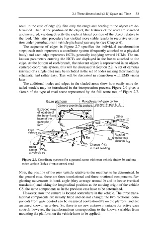
tailed models may be introduced in the interpretation process. Figure 2.9 gives a
sketch of the type of road scene represented by the full scene tree of Figure 2.7.
Gaze platform Movable part of gaze control
Camera coordinate system platform in pan & tilt
Exploded view xp
of location of y p \ c
the body-fixed y íT Other
base of the c x c c vehicle (o)
gaze plat - z c of road íy o
form z p stretch x Ro
Extended x y Ro
Own x b 'F R1
vehicle cg í\ r T b
b Road at
y R1 look -ahead
y b x Rb z Ro distance L
y Rb y z R1 Change 'F O
Road z b in road heading
center z Rb
at vehicle cg
Figure 2.9. Coordinate systems for a general scene with own vehicle (index b) and one
other vehicle (index o) on a curved road
Now, the position of the own vehicle relative to the road has to be determined. In
the general case, these are three translational and three rotational components. Ne-
glecting movements in bank angle (they average around 0) and in heave (vertical
translation) and taking the longitudinal position as the moving origin of the vehicle
CS, the same components as in the previous case have to be determined.
However, now the camera is located somewhere in the vehicle. The three trans-
lational components are usually fixed and do not change; the two rotational com-
ponents from gaze control can be measured conventionally on the platform and are
assumed known, error-free. So, there is no new unknown variable for active gaze
control; however, the transformations corresponding to the known variables from
mounting the platform on the vehicle have to be applied.