
Page 50 - Dynamic Vision for Perception and Control of Motion
P. 50
34 2 Basic Relations: Image Sequences – “the World”
For the more general case of a curved road (shaded area to the right in Figure
2.7), the road models to be discussed in later sections have to be applied. They in-
troduce several more unknowns into the vision process. However, using differen-
tial-geometry models minimizes the number of these terms; for planar roads, two
sets of additional CSs allow large look-ahead ranges even with up to two inflection
points of the road (changes of the sign of curvature; Figure 2.9 has just one).
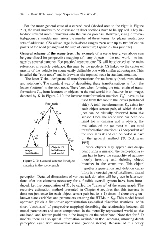
General scheme of the scene tree: The example of a scene tree given above can
be generalized for perspective mapping of many objects in the real world into im-
ages by several cameras. For practical reasons, one CS will be selected as the main
reference; in vehicle guidance, this may be the geodetic CS linked to the center of
gravity of the vehicle (or some easily definable one with similar advantages). This
is called the “root node” and is drawn as the topmost node in standard notation.
The letter T shall designate all transformations for uniformity (both translations
and rotations). The standard way of describing these transformations is from the
leaves (bottom) to the root node. Therefore, when forming the total chain of trans-
formations T tot from features on objects in the real world into features in an image,
í1
denoted by K in Figure 2.10, the inverse transformation matrices T kj have to be
used from the root to the leaves (left-hand
Root node side). A total transformation T tot exists for
each object-sensor pair, of which the ob-
í1
T k1 T Oi1 ject can be visually observed from the
sensor. Once the scene tree has been de-
T k2 í1 fined for m cameras and n objects, the
evaluation of the (at most n · m) total
.… …. …. ….
transformation matrices is independent of
the special task and can be coded as part
í1
T kjP
T of the general method [D. Dickmanns
OiQ
1997].
K j Objects O Since objects may appear and disap-
Image in 3-dimens. O i pear during a mission, the perception sys-
coordinates real world
tem has to have the capability of autono-
mously inserting and deleting object
Figure 2.10. General scheme for object
branches in the scene tree. This object
mapping in the scene graph
hypothesis generation and deletion capa-
bility is a crucial part of intelligent visual
perception. Detailed discussions of various task domains will be given in later sec-
tions after the elements necessary for a flexible overall system have been intro-
duced. Let the computation of T tot be called the “traverse” of the scene graph. The
recursive estimation method presented in Chapter 6 requires that this traverse is
done not just once for each object-sensor pair but (q + 1) times, if there are q un-
known state variables and parameters entering the HTMs in T tot. This model-based
approach yields a first-order approximation (so-called “Jacobian matrices” or in
short “Jacobians” of perspective mapping) describing the relationship between all
model parameters and state components in the mentally represented world on the
one hand, and feature positions in the images, on the other hand. Note that for 3-D
models, there is also spatial information available in the Jacobians, allowing depth
perception even with monocular vision (motion stereo). Because of this heavy