
Page 98 - Dynamic Vision for Perception and Control of Motion
P. 98
3 Subjects and Subject Classes
82
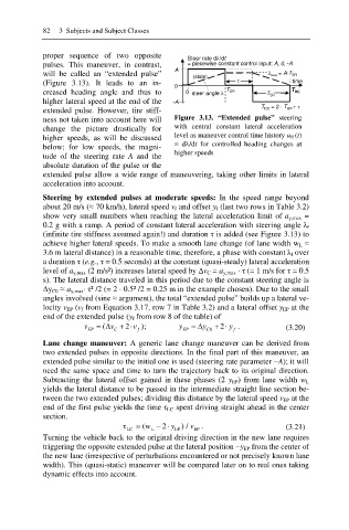
proper sequence of two opposite
Steer rate dO/dt
pulses. This maneuver, in contrast, = piecewise constant control input: A, 0, -A
A
will be called an “extended pulse” (state) Ȝ max = A·T SR
(Figure 3.13). It leads to an in- W time
0
creased heading angle and thus to 0 steer angle O T SR T SR T DC
higher lateral speed at the end of the -A
T DC = 2 · T SR + W
extended pulse. However, tire stiff-
ness not taken into account here will Figure 3.13. “Extended pulse” steering
change the picture drastically for with central constant lateral acceleration
higher speeds, as will be discussed level as maneuver control time history u ff (t)
=dO/dt for controlled heading changes at
below; for low speeds, the magni-
tude of the steering rate A and the higher speeds
absolute duration of the pulse or the
extended pulse allow a wide range of maneuvering, taking other limits in lateral
acceleration into account.
Steering by extended pulses at moderate speeds: In the speed range beyond
about 20 m/s (§ 70 km/h), lateral speed v f and offset y f (last two rows in Table 3.2)
show very small numbers when reaching the lateral acceleration limit of a y,max =
0.2 g with a ramp. A period of constant lateral acceleration with steering angle Ȝ f
(infinite tire stiffness assumed again!) and duration IJ is added (see Figure 3.13) to
achieve higher lateral speeds. To make a smooth lane change (of lane width w L §
3.6 m lateral distance) in a reasonable time, therefore, a phase with constant Ȝ f over
a duration IJ (e.g., IJ = 0.5 seconds) at the constant (quasi-steady) lateral acceleration
level of a y,max (2 m/s²) increases lateral speed by ǻv C = a y,max · IJ (= 1 m/s for IJ = 0.5
s). The lateral distance traveled in this period due to the constant steering angle is
ǻy C0 § a y,max· IJ² /2 (= 2 · 0.5² /2 = 0.25 m in the example chosen). Due to the small
angles involved (sine § argument), the total “extended pulse” builds up a lateral ve-
locity v EP (v f from Equation 3.17, row 7 in Table 3.2) and a lateral offset y EP at the
end of the extended pulse (y f from row 8 of the table) of
( v
v ' 2 v ); y ' y 2 y . (3.20)
EP C f EP C 0 f
Lane change maneuver: A generic lane change maneuver can be derived from
two extended pulses in opposite directions. In the final part of this maneuver, an
extended pulse similar to the initial one is used (steering rate parameter íA); it will
need the same space and time to turn the trajectory back to its original direction.
Subtracting the lateral offset gained in these phases (2 y EP) from lane width w L
yields the lateral distance to be passed in the intermediate straight line section be-
tween the two extended pulses; dividing this distance by the lateral speed v EP at the
end of the first pulse yields the time IJ LC spent driving straight ahead in the center
section.
IJ = (w EP ) / v . (3.21)
2 y
EP
LC
L
Turning the vehicle back to the original driving direction in the new lane requires
triggering the opposite extended pulse at the lateral position íy EP from the center of
the new lane (irrespective of perturbations encountered or not precisely known lane
width). This (quasi-static) maneuver will be compared later on to real ones taking
dynamic effects into account.