
Page 210 - Dynamics of Mechanical Systems
P. 210
0593_C06_fm Page 191 Monday, May 6, 2002 2:28 PM
Forces and Force Systems 191
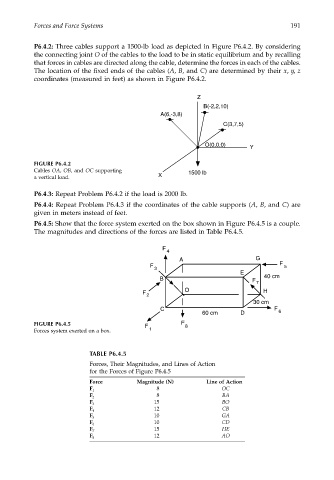
P6.4.2: Three cables support a 1500-lb load as depicted in Figure P6.4.2. By considering
the connecting joint O of the cables to the load to be in static equilibrium and by recalling
that forces in cables are directed along the cable, determine the forces in each of the cables.
The location of the fixed ends of the cables (A, B, and C) are determined by their x, y, z
coordinates (measured in feet) as shown in Figure P6.4.2.
Z
B(-2,2,10)
A(6,-3,8)
C(3,7,5)
O(0,0,0) Y
FIGURE P6.4.2
Cables OA, OB, and OC supporting 1500 lb
a vertical load. X
P6.4.3: Repeat Problem P6.4.2 if the load is 2000 lb.
P6.4.4: Repeat Problem P6.4.3 if the coordinates of the cable supports (A, B, and C) are
given in meters instead of feet.
P6.4.5: Show that the force system exerted on the box shown in Figure P6.4.5 is a couple.
The magnitudes and directions of the forces are listed in Table P6.4.5.
F
4
A G
F F 5
3
E
B F 40 cm
7
O H
F
2
30 cm
C F
60 cm D 6
FIGURE P6.4.5 F F 8
Forces system exerted on a box. 1
TABLE P6.4.5
Forces, Their Magnitudes, and Lines of Action
for the Forces of Figure P6.4.5
Force Magnitude (N) Line of Action
8 OC
F 1
8 BA
F 2
15 BO
F 3
12 CB
F 4
10 GA
F 5
10 CD
F 6
15 HE
F 7
12 AO
F 8