Page 213 - Dynamics of Mechanical Systems
P. 213

0593_C06_fm  Page 194  Monday, May 6, 2002  2:28 PM


                       194                                                 Dynamics of Mechanical Systems


                       gravitational forces acting on these bodies are represented by equivalent gravity (weight)
                       force systems consisting of single vertical forces  W ,  W , and  W  as in Figure P6.7.1B.
                                                                                  3
                                                                         2
                                                                      1
                       Finally, suppose we want to find an equivalent gravity force system for the entire arm
                       consisting of a single force W passing through the shoulder joint O together with a couple
                       with torque M. Find W and M. Express the results in terms of the angles θ , θ , and θ ;
                                                                                              2
                                                                                                     3
                                                                                           1
                       the distances r , r , r ,   ,   , and   ; the force magnitudes W , W , and W ; and the unit
                                                                                 2
                                                      3
                                                                                         3
                                            1
                                               2
                                      2
                                         3
                                                                             1
                                    1
                       vectors n , n , and n  shown in Figures P6.7.1A and B.
                                  y
                                         z
                               x
                       P6.7.2: See Problem P6.7.1. Table P6.7.2 provides numerical values for the geometric
                       quantities and weights of the arm model of Figures P6.7.1A and B. Using these values,
                       determine the magnitudes of W and M.
                                    TABLE P6.7.2
                                    Numerical Values for the Geometric Parameters and Weights
                                    of Figures P6.7.1A and B
                                    i        θθ θ θ  (°)  r i  (in.)     i  (in.)  W i  (lb)
                                             i
                                    1         45           4.45         11.7        5.0
                                    2         15           6.5          14.5        3.0
                                    3         30           2.5           6.0        1.15
                       P6.7.3: See Problems P6.7.1 and P6.7.2. Suppose the equivalent force system is to be a
                       wrench, where the couple torque M is a minimum. Locate a point G on the line of action
                       of the equivalent force. Find the magnitudes of the equivalent wrench force and minimum
                       moment.
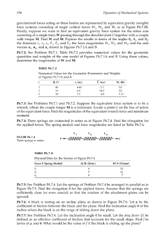
                       P6.7.4: Three springs are connected in series as in Figure P6.7.4. Find the elongation for
                       the applied forces. The spring moduli and force magnitudes are listed in Table P6.7.4.
                                                         k        k        k
                                                          1        2        3
                       FIGURE P6.7.4
                       Three springs in series.  F                                  F


                                 TABLE P6.7.4
                                 Physical Data for the System of Figure P6.7.4
                                 Force F Spring Moduli       12 lb (lb/in.)     50 N (N/mm)
                                                                  6                  10
                                 k 1
                                                                  5                  12
                                 k 2
                                                                  8                   7
                                 k 3
                       P6.7.5: See Problem P6.7.4. Let the springs of Problem P6.7.4 be arranged in parallel as in
                       Figure P6.7.5. Find the elongation δ for the applied forces. Assume that the springs are
                       sufficiently close (or even coaxial) so that the rotation of the attachment plates can be
                       ignored.
                       P6.7.6: A block is resting on an incline plane as shown in Figure P6.7.6. Let  µ be the
                       coefficient of friction between the block and the plane. Find the inclination angle θ of the
                       incline where the block is on the verge of sliding down the plane.
                       P6.7.7: See Problem P6.7.6. Let the inclination angle θ be small. Let the drag factor (f) be
                       defined as an effective coefficient of friction that accounts for the small slope. Find f in
                       terms of µ and θ. What would be the value of f if the block is sliding up the plane?
   208   209   210   211   212   213   214   215   216   217   218