
Page 214 - Dynamics of Mechanical Systems
P. 214
0593_C06_fm Page 195 Monday, May 6, 2002 2:28 PM
Forces and Force Systems 195
k
1
k
2
F F
k
3
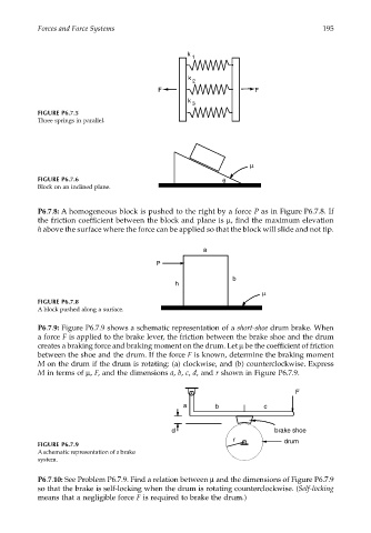
FIGURE P6.7.5
Three springs in parallel.
µ
FIGURE P6.7.6 θ
Block on an inclined plane.
P6.7.8: A homogeneous block is pushed to the right by a force P as in Figure P6.7.8. If
the friction coefficient between the block and plane is µ, find the maximum elevation
h above the surface where the force can be applied so that the block will slide and not tip.
a
P
b
h
µ
FIGURE P6.7.8
A block pushed along a surface.
P6.7.9: Figure P6.7.9 shows a schematic representation of a short-shoe drum brake. When
a force F is applied to the brake lever, the friction between the brake shoe and the drum
creates a braking force and braking moment on the drum. Let µ be the coefficient of friction
between the shoe and the drum. If the force F is known, determine the braking moment
M on the drum if the drum is rotating: (a) clockwise, and (b) counterclockwise. Express
M in terms of µ, F, and the dimensions a, b, c, d, and r shown in Figure P6.7.9.
F
a b c
d brake shoe
r drum
FIGURE P6.7.9
A schematic representation of a brake
system.
P6.7.10: See Problem P6.7.9. Find a relation between µ and the dimensions of Figure P6.7.9
so that the brake is self-locking when the drum is rotating counterclockwise. (Self-locking
means that a negligible force F is required to brake the drum.)