
Page 216 - Dynamics of Mechanical Systems
P. 216
0593_C06_fm Page 197 Monday, May 6, 2002 2:28 PM
Forces and Force Systems 197
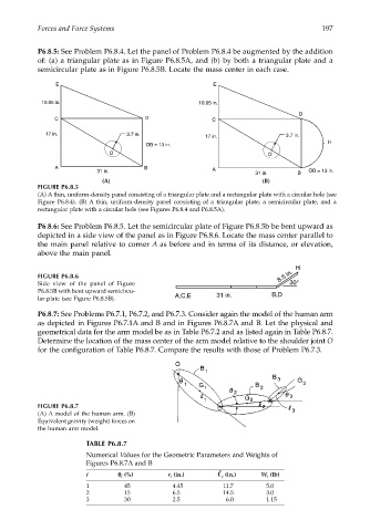
P6.8.5: See Problem P6.8.4. Let the panel of Problem P6.8.4 be augmented by the addition
of: (a) a triangular plate as in Figure P6.8.5A, and (b) by both a triangular plate and a
semicircular plate as in Figure P6.8.5B. Locate the mass center in each case.
E E
10.05 in. 10.05 in.
D
C D C
17 in. 3.7 in. 3.7 in.
17 in.
H
OB = 13 in.
O O
A B A
31 in. OB = 13 in.
31 in. B
(A) (B)
FIGURE P6.8.5
(A) A thin, uniform-density panel consisting of a triangular plate and a rectangular plate with a circular hole (see
Figure P6.8.4). (B) A thin, uniform-density panel consisting of a triangular plate, a semicircular plate, and a
rectangular plate with a circular hole (see Figures P6.8.4 and P6.8.5A).
P6.8.6: See Problem P6.8.5. Let the semicircular plate of Figure P6.8.5b be bent upward as
depicted in a side view of the panel as in Figure P6.8.6. Locate the mass center parallel to
the main panel relative to corner A as before and in terms of its distance, or elevation,
above the main panel.
H
FIGURE P6.8.6 8.5 in.
Side view of the panel of Figure 30°
P6.8.5B with bent upward semicircu- B,D
lar plate (see Figure P6.8.5B). A,C,E 31 in.
P6.8.7: See Problems P6.7.1, P6.7.2, and P6.7.3. Consider again the model of the human arm
as depicted in Figures P6.7.1A and B and in Figures P6.8.7A and B. Let the physical and
geometrical data for the arm model be as in Table P6.7.2 and as listed again in Table P6.8.7.
Determine the location of the mass center of the arm model relative to the shoulder joint O
for the configuration of Table P6.8.7. Compare the results with those of Problem P6.7.3.
FIGURE P6.8.7
(A) A model of the human arm. (B)
Equivalent gravity (weight) forces on
the human arm model.
TABLE P6.8.7
Numerical Values for the Geometric Parameters and Weights of
Figures P6.8.7A and B
i θθ θ θ (%) r i (in.) i (in.) W i (lb)
i
1 45 4.45 11.7 5.0
2 15 6.5 14.5 3.0
3 30 2.5 6.0 1.15