
Page 318 - Dynamics of Mechanical Systems
P. 318
0593_C09_fm Page 299 Monday, May 6, 2002 2:50 PM
Principles of Impulse and Momentum 299
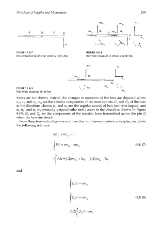
FIGURE 9.8.7 FIGURE 9.8.8
Pin-connected double bar struck at one end. Free-body diagram of struck double bar.
FIGURE 9.8.9
Free-body diagram of left bar.
forces are not shown. Instead, the changes in momenta of the bars are depicted where
v , v and v , v are the velocity components of the mass centers, G and G , of the bars
1x 1y 2x 2y 1 2
in the directions shown; ω and ω are the angular speeds of bars just after impact; and
1 2
n , n , and n are mutually perpendicular unit vectors in the directions shown. In Figure
x y z
9.8.9, Q and Q are the components of the reaction force transmitted across the pin Q
x y
when the bars are struck.
From these free-body diagrams and from the impulse–momentum principles, we obtain
the following relations:
mv + mv = 0
1 x 2 x
t
∫ Pdt = mv + mv 2 y (9.8.17)
1
y
0
t
−
l ∫ Pdt =(l 2) mv + Iω 2 (l 2) mv + Iω 1
1
y
2
y
0
and
t
∫ Qdt = mv 1 x
x
0
t
∫ Qdt = mv 1 y (9.8.18)
y
0
t
( ) 2l ∫ Qdt = Iω 1
y
0