
Page 316 - Dynamics of Mechanical Systems
P. 316
0593_C09_fm Page 297 Monday, May 6, 2002 2:50 PM
Principles of Impulse and Momentum 297
where I is the axial moment of inertia of W (the moment of inertia of W about O for the
O
axial direction). Then from the angular impulse–momentum principle the angular speed
of W after braking is determined by the expressions:
−
J = ∆ A or M max T k = I ω k I ω O k (9.8.7)
O
O
O
O
or
ω = M T I (9.8.8)
O max O
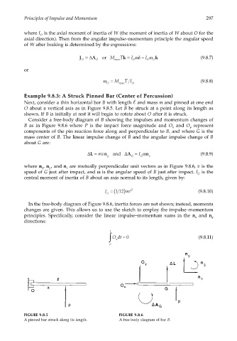
Example 9.8.3: A Struck Pinned Bar (Center of Percussion)
Next, consider a thin horizontal bar B with length and mass m and pinned at one end
O about a vertical axis as in Figure 9.8.5. Let B be struck at a point along its length as
shown. If B is initially at rest it will begin to rotate about O after it is struck.
Consider a free-body diagram of B showing the impulses and momentum changes of
B as in Figure 9.8.6 where P is the impact force magnitude and O and O represent
y
x
components of the pin reaction force along and perpendicular to B, and where G is the
mass center of B. The linear impulse change of B and the angular impulse change of B
about G are:
∆L = mv n and ∆A = I ω n (9.8.9)
y G G z
where n , n , and n are mutually perpendicular unit vectors as in Figure 9.8.6, v is the
x
y
z
speed of G just after impact, and ω is the angular speed of B just after impact. I is the
G
central moment of inertia of B about an axis normal to its length, given by:
I = (112 m ) l 2 (9.8.10)
G
In the free-body diagram of Figure 9.8.6, inertia forces are not shown; instead, momenta
changes are given. This allows us to use the sketch to employ the impulse–momentum
principles. Specifically, consider the linear impulse–momentum sums in the n and n y
x
directions:
t
∫ Odt = 0 (9.8.11)
x
0
FIGURE 9.8.5 FIGURE 9.8.6
A pinned bar struck along its length. A free-body diagram of bar B.