Page 315 - Dynamics of Mechanical Systems
P. 315

0593_C09_fm  Page 296  Monday, May 6, 2002  2:50 PM


                       296                                                 Dynamics of Mechanical Systems


                       where n is a unit vector parallel to the support as in Figure 9.8.1. Let the velocity of B
                       before and after the application of F be V n and Vn, respectively. Then, from the linear
                                                            O
                       impulse–momentum principle, we have:


                                                             ˆ
                                              I = ∆ L   or   F max ( t 2  n ) = mV n − mV O n   (9.8.2)
                       or


                                                       V = V +  F  t 2 m                        (9.8.3)
                                                                  ˆ
                                                           O   max
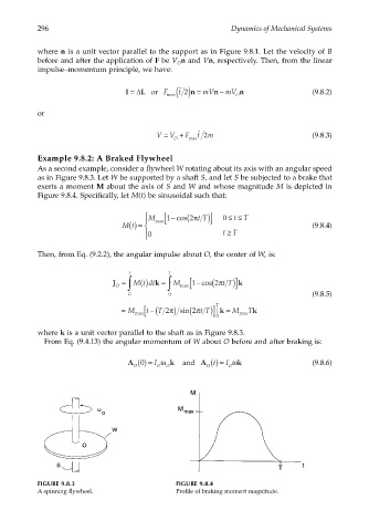
                       Example 9.8.2: A Braked Flywheel
                       As a second example, consider a flywheel W rotating about its axis with an angular speed
                       as in Figure 9.8.3. Let W be supported by a shaft S, and let S be subjected to a brake that
                       exerts a moment M about the axis of S and W and whose magnitude M is depicted in
                       Figure 9.8.4. Specifically, let M(t) be sinusoidal such that:

                                                               (
                                                    M   [ 1 − cos 2π t T)]  0 ≤≤
                                                                           tT
                                                   
                                             Mt () =   max                                     (9.8.4)
                                                                          ≥
                                                   0                   tT
                                                   
                       Then, from Eq. (9.2.2), the angular impulse about O, the center of W, is:
                                               T          T
                                                  ()
                                           J = ∫  M t dt k = ∫  M max [ 1 − cos (2π t T)] k
                                            O
                                               0          0                                     (9.8.5)
                                             =  M  [ t −( T 2π ) sin (2π t T)] T | k =  M  T k
                                                 max
                                                                       0     max
                       where k is a unit vector parallel to the shaft as in Figure 9.8.3.
                        From Eq. (9.4.13) the angular momentum of W about O before and after braking is:

                                               A 0 () =  I ω  k     and    A t () = I ω k       (9.8.6)
                                                O      O  O         O     O


                       FIGURE 9.8.3                         FIGURE 9.8.4
                       A spinning flywheel.                  Profile of braking moment magnitude.
   310   311   312   313   314   315   316   317   318   319   320