
Page 311 - Dynamics of Mechanical Systems
P. 311
0593_C09_fm Page 292 Monday, May 6, 2002 2:50 PM
292 Dynamics of Mechanical Systems
where we have used Eq. (4.6.6). If I B/G is expressed in terms of unit vectors fixed in B, its
B
components relative to these vectors are constant. Hence, dI B/G /dt is zero. Also, the third
R
term is zero. Therefore, dA B/O /dt becomes:
α
ω
ω
R dt = BG ⋅ +αωω × I ( BG ⋅ ) + P × G
dA BO I G ma (9.6.21)
where αα αα is the angular acceleration of B in R. (Note from Eq. (4.6.6) that dωω ωω/dt =
R
B dωω ωω/dt = αα αα.)
Next, for A B/Q we have:
d QG ×
R dt = ( B G ⋅ωω dt ) + ( mv )
R
G
R
dA d I dt
BQ
ωω
= B d I ( B G ⋅ωω dt ) + ωω × I ( B G ⋅ )
+ v GQ × mv + QG × ma G (9.6.22)
G
ααωω
= I BG ⋅ + × I ( BG ⋅ ) − v × mv G
ωω
Q
+ QG × ma G
Finally, for A B/G we have:
ωω
ωω
R dt = ( B G ⋅ ) dt = B BG dt + ωω × I ( BG ⋅ )
R
dA d I dI
BG
(9.6.23)
ωω
ααωω
= I BG ⋅ + × I ( BG ⋅ )
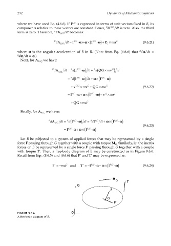
Let B be subjected to a system of applied forces that may be represented by a single
force F passing through G together with a couple with torque M . Similarly, let the inertia
G
*
forces on B be represented by a single force F passing through G together with a couple
with torque T . Then, a free-body diagram of B may be constructed as in Figure 9.6.6.
*
*
*
Recall from Eqs. (8.6.5) and (8.6.6) that F and T may be expressed as:
ωω
α
*
*
G
F =−m a and T =− I B G ⋅ −αωω × I ( B G ⋅ ) (9.6.24)
FIGURE 9.6.6
A free-body diagram of B.