
Page 310 - Dynamics of Mechanical Systems
P. 310
0593_C09_fm Page 291 Monday, May 6, 2002 2:50 PM
Principles of Impulse and Momentum 291
By integrating over the time interval in which the forces are applied, we have:
t 2 t 2
∫ M dt = ∫ ( d A SQ ) A () − A ()
dt dt =
t
t
SQ
Q
SQ
2
1
t 1 t 1
or
J =∆ A (9.6.16)
Q S Q
where here J represents the sum of the angular impulses of the applied forces about Q
Q
during the time interval (t , t ). Hence, as with a single particle, the angular impulse about
2
1
a point Q fixed in an inertial reference frame is equal to the change in angular momentum
of the set of particles about Q.
Finally, consider a rigid body B moving in an inertial reference frame R as in Figure
9.6.5. Let G be the mass center of B, let Q be a reference point, and let O be the origin of
R. Then, from Eqs. (9.4.8), (9.4.12), and (9.4.13), the angular momenta of B about O, Q,
and G are:
A = A + A = I BG ⋅ωω + P × m v G (9.6.17)
BO B G G O G
×
A = A + A = I BG ⋅ωω + QG m v G (9.6.18)
BQ B G G Q
A = I BG ⋅ωω (9.6.19)
BG
where P and QG locate G relative to O and Q as in Figure 9.6.5, and where as before ωω ωω
G
is the angular velocity of B in R, I B/G is the central inertia dyadic of B, and m is the mass
of B. Consider the derivatives of these momenta. For A B/O we have:
G (
ωω
R dA BO dt = ( B G ⋅ ) dt + R d P × mv ) dt
G
R
d I
ωω
= B d I ( B G ⋅ ) dt + ωω × I ( B G ⋅ ) (9.6.20)
ωω
+ v × mv + P × ma G
G G G
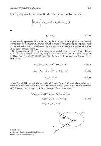
FIGURE 9.6.5
A rigid body B moving in an inertial reference
frame R and a reference point Q.