Page 402 - Dynamics of Mechanical Systems
P. 402

0593_C11_fm  Page 383  Monday, May 6, 2002  2:59 PM


                       Generalized Dynamics: Kinematics and Kinetics                               383


                                           v G 1  = (l  2)  n =−(l  2)  sinθ 1  n +(l  2)  cosθ 1  n 2
                                                      θ 1
                                                                    1
                                            ˙ θ 1
                                           v G 2  = l  n = −l sinθ  n + l cosθ  n
                                            ˙ θ 1  θ 1     1  1      1  2
                                                                                              (11.10.19)
                                           v G 1  =  0
                                            ˙ θ 2
                                           v G 2  = (l  2)  n  θ  =−(l  2)  sinθ  n +(l  2)  cosθ  n
                                            ˙ θ 2    2            2  1          2  2

                       and

                                                                  1 B
                                                                          B
                                               1 B
                                                        B
                                             ωω = n  ,  ωω =  0  ,  ωω =  0  ,  ωω = n        (11.10.20)
                                                                          2
                                                         2
                                               ˙ θ 1  3  ˙ θ 1   ˙ θ 2    ˙ θ 2  3
                        Finally, from Eq. (11.9.6) the generalized inertia forces are:
                                                         θ cos(
                                              θ −(
                                 F =−( 4 3)ml 2 ˙˙  12)ml 2 ˙˙  θ − ) +( 12)ml 2 2 ˙ θ sin( θ − )  (11.10.21)
                                                                                       θ
                                                                  θ
                                  *
                                  θ 1          1          2     2  1           2     2  1
                       and
                                 F =−( 13)ml 2 ˙˙ θ −( 12)ml 2 ˙˙  θ − ) −( 12)ml 2 2 ˙ θ sin( θ − )  (11.10.22)
                                                         θ cos(
                                                                                       θ
                                                                  θ
                                  θ 2 *        2          1     2  1           1    2   1
                        Observe how routine the computation is; the principal difficulty is the detail. We will
                       discuss this later.
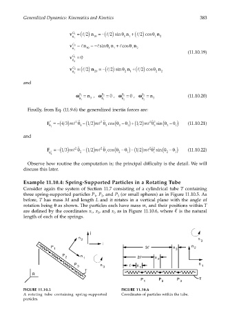
                       Example 11.10.4: Spring-Supported Particles in a Rotating Tube
                       Consider again the system of Section 11.7 consisting of a cylindrical tube T containing
                       three spring-supported particles P , P , and P  (or small spheres) as in Figure 11.10.5. As
                                                     1
                                                        2
                                                               3
                       before, T has mass M and length L and it rotates in a vertical plane with the angle of
                       rotation being θ as shown. The particles each have mass m, and their positions within T
                       are defined by the coordinates x , x , and x  as in Figure 11.10.6, where   is the natural
                                                       2
                                                              3
                                                    1
                       length of each of the springs.
                                                   j
                                              n
                                               2                                                  n  3
                                                         i
                                   P                                       3           x       n  2
                                    1                                                   3

                                       P       n
                                         2      1                       2      x
                                                                                 2
                                             P          n               x                         n
                                              3          3               1                         1
                                                 T
                          R
                                                                         P       P       P        T
                                                                          1       2       3
                       FIGURE 11.10.5                            FIGURE 11.10.6
                       A rotating tube containing spring-supported  Coordinates of particles within the tube.
                       particles.
   397   398   399   400   401   402   403   404   405   406   407