Page 417 - Dynamics of Mechanical Systems
P. 417
0593_C11_fm  Page 398  Monday, May 6, 2002  2:59 PM


                       398                                                 Dynamics of Mechanical Systems


                                                   j
                        O                                                                         n
                               P                        i                                          3
                                1
                                                 n                                             n
                           θ        P             2                         3           x  3     2
                                     2
                                                                         2      x
                                         P            n  3                       2
                                          3       n                                                n
                                              T    1                     x  1                       1
                          R
                                                                          P       P      P         T
                                                                           1       2       3
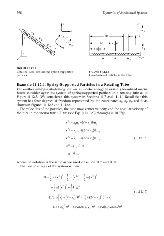
                       FIGURE 11.12.5
                       Rotating tube containing spring-supported   FIGURE 11.12.6
                       particles.                                  Coordinates of particles in the tube.

                       Example 11.12.4: Spring-Supported Particles in a Rotating Tube
                       For another example illustrating the use of kinetic energy to obtain generalized inertia
                       forces, consider again the system of spring-supported particles in a rotating tube as in
                       Figure 11.12.5. (We considered this system in Sections 11.7 and 11.11.) Recall that this
                       system has four degrees of freedom represented by the coordinates x , x , x , and θ, as
                                                                                         2
                                                                                      1
                                                                                            3
                       shown in Figures 11.12.5 and 11.12.6.
                        The velocities of the particles, the tube mass center velocity, and the angular velocity of
                       the tube in the inertia frame R are (see Eqs. (11.10.23) through (11.10.27)):
                                                    v = ˙ x  n +(l + x )θ ˙  n
                                                      P 1
                                                          11       1   2
                                                               2 +
                                                    v = ˙ x  n +( l  x )θ ˙  n
                                                      P 2
                                                          2  1      2   2
                                                               3 +
                                                    v = ˙ x  n +( l  x )θ ˙  n                (11.12.16)
                                                      P 3
                                                          3  1      3   3
                                                     v = ( L 2)θ ˙  n
                                                      G
                                                                2
                                                     ωω  = θ ˙  n
                                                           3
                       where the notation is the same as we used in Section 11.7 and 11.11.
                        The kinetic energy of the system is then:


                                                  2
                                                             2
                                       K =  1  m  v ( ) +  1  m  v ( ) +  1  m  v ( ) 2
                                                 1 P
                                                           2 P
                                                                     3 P
                                           2         2         2
                                                       1
                                                          ()
                                                    2
                                           +  1  M  v ( ) + I ωω  2
                                                   G
                                             2         2
                                                                                              (11.12.17)
                                                          2
                                                                          2
                                         = ( )mx ˙  2  +(l + ) θ 2 ˙  + x ˙  2  +(2l + ) θ 2 ˙  + x ˙  2
                                                                       x
                                           12
                                                        x
                                                [ 1      1      2       2      3
                                                    2
                                                                   2
                                                                    θ
                                           +(3l + ) θ 2 ˙  ] +( ) ( ) 2 θ +( )(     2 2 ˙ θ
                                                                     ˙ 2
                                                         1 2 M L
                                                                         12 1 12) ML
                                                 x
                                                  3

