
Page 225 - Electric Drives and Electromechanical Systems
P. 225
Chapter 8 Stepper motors 221
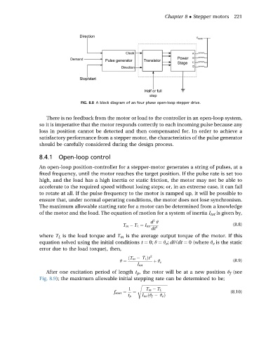
FIG. 8.8 A block diagram of an four phase open-loop stepper drive.
There is no feedback from the motor or load to the controller in an open-loop system,
so it is imperative that the motor responds correctly to each incoming pulse because any
loss in position cannot be detected and then compensated for. In order to achieve a
satisfactory performance from a stepper motor, the characteristics of the pulse generator
should be carefully considered during the design process.
8.4.1 Open-loop control
An open-loop position-controller for a stepper-motor generates a string of pulses, at a
fixed frequency, until the motor reaches the target position. If the pulse rate is set too
high, and the load has a high inertia or static friction, the motor may not be able to
accelerate to the required speed without losing steps; or, in an extreme case, it can fail
to rotate at all. If the pulse frequency to the motor is ramped up, it will be possible to
ensure that, under normal operating conditions, the motor does not lose synchronism.
The maximum allowable starting rate for a motor can be determined from a knowledge
of the motor and the load. The equation of motion for a system of inertia I tot is given by,
2
d q
T m T L ¼ I tot 2 (8.8)
dt
where T L is the load torque and T m is the average output torque of the motor. If this
equation solved using the initial conditions t ¼ 0; q ¼ q e ; dq/dt ¼ 0 (where q e is the static
error due to the load torque), then,
ðT m T L Þt 2
q ¼ þ q e (8.9)
I tot
After one excitation period of length t p , the rotor will be at a new position q f (see
Fig. 8.9); the maximum allowable initial stepping rate can be determined to be;
s ffiffiffiffiffiffiffiffiffiffiffiffiffiffiffiffiffiffiffiffiffiffiffiffiffiffiffi
1 T m T L
f start ¼ ¼ (8.10)
t p I tot ðq f q e Þ