
Page 226 - Electric Drives and Electromechanical Systems
P. 226
222 Electric Drives and Electromechanical Systems
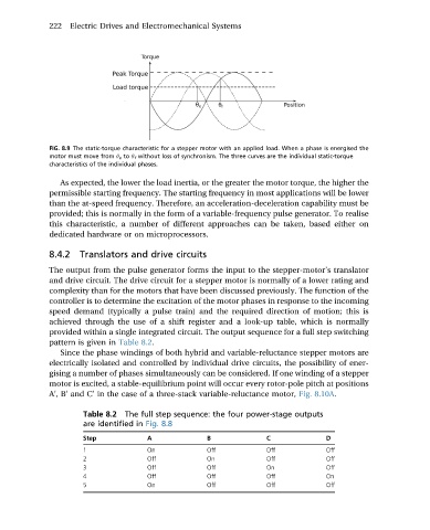
FIG. 8.9 The static-torque characteristic for a stepper motor with an applied load. When a phase is energised the
motor must move from q e to q f without loss of synchronism. The three curves are the individual static-torque
characteristics of the individual phases.
As expected, the lower the load inertia, or the greater the motor torque, the higher the
permissible starting frequency. The starting frequency in most applications will be lower
than the at-speed frequency. Therefore, an acceleration-deceleration capability must be
provided; this is normally in the form of a variable-frequency pulse generator. To realise
this characteristic, a number of different approaches can be taken, based either on
dedicated hardware or on microprocessors.
8.4.2 Translators and drive circuits
The output from the pulse generator forms the input to the stepper-motor’s translator
and drive circuit. The drive circuit for a stepper motor is normally of a lower rating and
complexity than for the motors that have been discussed previously. The function of the
controller is to determine the excitation of the motor phases in response to the incoming
speed demand (typically a pulse train) and the required direction of motion; this is
achieved through the use of a shift register and a look-up table, which is normally
provided within a single integrated circuit. The output sequence for a full step switching
pattern is given in Table 8.2.
Since the phase windings of both hybrid and variable-reluctance stepper motors are
electrically isolated and controlled by individual drive circuits, the possibility of ener-
gising a number of phases simultaneously can be considered. If one winding of a stepper
motor is excited, a stable-equilibrium point will occur every rotor-pole pitch at positions
A ,B and C’ in the case of a three-stack variable-reluctance motor, Fig. 8.10A.
0
0
Table 8.2 The full step sequence: the four power-stage outputs
are identified in Fig. 8.8
Step A B C D
1 On Off Off Off
2 Off On Off Off
3 Off Off On Off
4 Off Off Off On
5 On Off Off Off