
Page 262 - Electric Drives and Electromechanical Systems
P. 262
Chapter 10 Controllers for automation 259
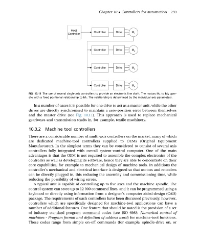
FIG. 10.11 The use of several single-axis controllers to provide an electronic line shaft. The motors M 2 to M 4 oper-
ate with a fixed positional relationship to M 1 . The relationship is determined by the individual axis parameters.
In a number of cases it is possible for one drive to act as a master unit, while the other
drives are directly synchronised to maintain a zero-position error between themselves
and the master drive (see Fig. 10.11). This approach is used to replace mechanical
gearboxes and transmission shafts in, for example, textile machinery.
10.3.2 Machine tool controllers
There are a considerable number of multi-axis controllers on the market, many of which
are dedicated machine-tool controllers supplied to OEMs (Original Equipment
Manufacturer). In the simplest terms they can be considered to consist of several axis
controllers fully integrated with overall system-control computer. One of the main
advantages is that the OEM is not required to assemble the complex electronics of the
controller as well as developing its software, hence they are able to concentrate on their
core capabilities, for example to mechanical design of machine tools. In additions the
controller’s mechanical and electrical interface is designed so that motors and encoders
can be directly plugged in, this reducing the assembly and commissioning time, while
reducing the possibility of wiring errors.
A typical unit is capable of controlling up to five axes and the machine spindle. The
control system can store up to 12 000 command lines, and it can be programmed using a
keyboard or directly using information from a designer’s computer aided-design (CAD)
package. The requirements of such controllers have been discussed previously; however,
controllers which are specifically designed for machine-tool applications can have a
number of additional features. One feature that should be noted is the provision of a set
of industry standard program command codes (see ISO 6983: Numerical control of
machines - Program format and definition of address word) for machine-tool functions.
These codes range from simple on-off commands (for example, spindle-drive on, or