
Page 264 - Electric Drives and Electromechanical Systems
P. 264
Chapter 10 Controllers for automation 261
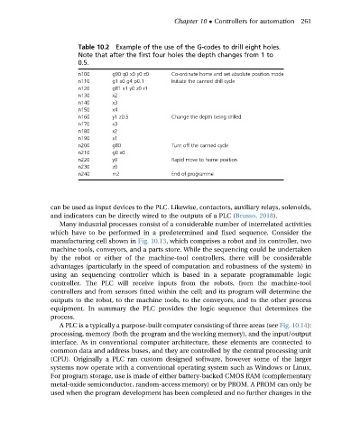
Table 10.2 Example of the use of the G-codes to drill eight holes.
Note that after the first four holes the depth changes from 1 to
0.5.
n100 g90 g0 x0 y0 z0 Co-ordinate home and set absolute position mode
n110 g1 x0 g4 p0.1 Initiate the canned drill cycle
n120 g81 x1 y0 z0 r1
n130 x2
n140 x3
n150 x4
n160 y1 z0.5 Change the depth being drilled
n170 x3
n180 x2
n190 x1
n200 g80 Turn off the canned cycle
n210 g0 x0
n220 y0 Rapid move to home position
n230 z0
n240 m2 End of programme
can be used as input devices to the PLC. Likewise, contactors, auxiliary relays, solenoids,
and indicators can be directly wired to the outputs of a PLC (Brusso, 2018).
Many industrial processes consist of a considerable number of interrelated activities
which have to be performed in a predetermined and fixed sequence. Consider the
manufacturing cell shown in Fig. 10.13, which comprises a robot and its controller, two
machine tools, conveyors, and a parts store. While the sequencing could be undertaken
by the robot or either of the machine-tool controllers, there will be considerable
advantages (particularly in the speed of computation and robustness of the system) in
using an sequencing controller which is based in a separate programmable logic
controller. The PLC will receive inputs from the robots, from the machine-tool
controllers and from sensors fitted within the cell; and its program will determine the
outputs to the robot, to the machine tools, to the conveyors, and to the other process
equipment. In summary the PLC provides the logic sequence that determines the
process.
A PLC is a typically a purpose-built computer consisting of three areas (see Fig. 10.14):
processing, memory (both the program and the working memory), and the input/output
interface. As in conventional computer architecture, these elements are connected to
common data and address buses, and they are controlled by the central processing unit
(CPU). Originally a PLC ran custom designed software, however some of the larger
systems now operate with a conventional operating system such as Windows or Linux.
For program storage, use is made of either battery-backed CMOS RAM (complementary
metal-oxide semiconductor, random-access memory) or by PROM. A PROM can only be
used when the program development has been completed and no further changes in the