Page 269 - Electric Drives and Electromechanical Systems
P. 269

266   Electric Drives and Electromechanical Systems


                              Table 10.4  Instructions for the ladder logic
                              shown in Fig. 10.16
                              LD                                           X0
                              OR                                           X1
                              OR                                           X2
                              AND                                          X3
                              AND                                          X4
                              OR                                           X5
                              OUT                                          Y1


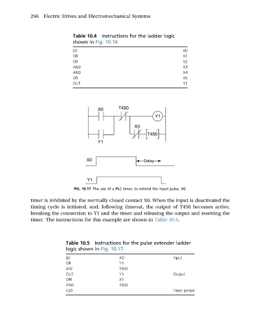
                               FIG. 10.17 The use of a PLC timer, to extend the input pulse, X0.

             timer is inhibited by the normally closed contact X0. When the input is deactivated the
             timing cycle is initiated, and, following timeout, the output of T450 becomes active,
             breaking the connection to Y1 and the timer and releasing the output and resetting the
             timer. The instructions for this example are shown in Table 10.5.


                            Table 10.5  Instructions for the pulse extender ladder
                            logic shown in Fig. 10.17.
                            LD                   XO                    Input
                            OR                   Y1
                            ANI                  T450
                            OUT                  Y1                    Output
                            ORI                  X1
                            AND                  T450
                            K20                                        Timer period
   264   265   266   267   268   269   270   271   272   273   274