
Page 272 - Electric Drives and Electromechanical Systems
P. 272
Chapter 10 Controllers for automation 269
which is signalled by a fourth limit switch, LS4. When the component has clearing the
process, the belt is restarted, and the next component is moved up to the first limit
switch, LS1. The required PLC process can be expressed in four states, S 1 to S 4 with the
following Boolean relationships:
S1 ¼ S4 $ LS4 þ S1 $ S2
S2 ¼ S1 $ LS1 þ S2 $ S3 (10.18)
S3 ¼ S2 $ LS2 þ S3 $ S4
S4 ¼ S3 $ LS3 þ S4 $ S1
In order to initiate a state (for example State 1, the movement of the belt), the
previous state (in this case State 4) has to be valid and a limit switch (LS4) has to be
activated. State 1 is held until State 2 is initialled by LS1. It should be noted that one state
is entered before the previous state is exited; in practice this is only a transitory phase
and it should not cause any conflict in the operating process. Using this information, the
ladder diagram can be constructed (see Fig. 10.14), which in turn can be coded for the
PLC. One problem that needs to be addressed is to ensure that the sequence is always
started in State 1. This is achieved by the addition of a start control relay, M105. On
powering up, the system is therefore forced into State 1. On entering State 3, the control
relay M105 is latched via M103 and it is isolated. The functions of the control relays and
the inputs are summarised in Table 10.6.
For a practical implementation, additional steps must be included, for example,
interfacing of the control relays to the conveyor drive and any required pneumatic or
hydraulic control valves, the implementation of safety circuits, and process control and
manual-override provision. While this effectively discrete approach is satisfactory for
small systems, it can be simplified by the use of PLC functions such as shift registers,
control relays, step ladder functions drum times and sequences. The operation of these
programming blocks will be detailed in the manufacturer’s literature. While these
examples can be considered to be relatively trivial, they do show the power of modern
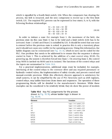
Table 10.6 Key PLC assignments for the process
shown in Fig. 10.18, whose ladder logic is shown in
Fig. 10.19.
Element Function
X1 Input: limit switch, LS1
X2 Input: limit switch, LS2
X3 Input: limit switch, LS3
X4 Input: limit switch, LS4
M101 State 1 control relay
M102 State 2 control relay
M103 State 3 control relay
M104 State 4 control relay
M105 Start control relay