
Page 270 - Electric Drives and Electromechanical Systems
P. 270
Chapter 10 Controllers for automation 267
Timers can also be used to provide delays, control program sequencing, and to
generate programmable mark/space-ratio pulse trains. In addition, a PLC will also
contain blocks to provide down counters, auxiliary relays, and other features that will
assist the program development.
10.4.2 Sequential logic programming
The outputs in a sequential-control strategy do not only depend on the present inputs,
they also depend on the sequence of the previous events; hence some form of memory is
required to implement this approach. Sequential problems can be solved using
conventional logic networks. However, modern PLCs have a number of features,
particularly shift registers and drum timers, that considerably simplify the program
structure. As with digital electronics, sequential-logic requires a different approach than
is used in the design of combinational logic. The key steps are:
The functionality of the process needs to be carefully and fully described.
The description then needs to be developed into a fully descriptive functional diagram.
The function diagram is converted to the required Boolean logic.
The Boolean logic is converted to a ladder diagram and then into required code for
the PLC.
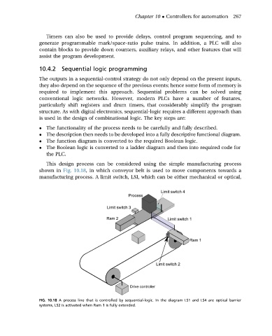
This design process can be considered using the simple manufacturing process
shown in Fig. 10.18, in which conveyor belt is used to move components towards a
manufacturing process. A limit switch, LSI, which can be either mechanical or optical,
FIG. 10.18 A process line that is controlled by sequential-logic. In the diagram LS1 and LS4 are optical barrier
systems, LS2 is activated when Ram 1 is fully extended.