
Page 268 - Electric Drives and Electromechanical Systems
P. 268
Chapter 10 Controllers for automation 265
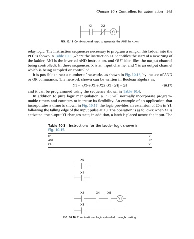
FIG. 10.15 Combinational logic to generate the AND function.
relay logic. The instruction sequences necessary to program a rung of this ladder into the
PLC is shown in Table 10.3 (where the instruction LD identifies the start of a new rung of
the ladder, ANI is the inverted AND instruction, and OUT identifies the output channel
being controlled). In these sequences, X is an input channel and Y is an output channel
which is being sampled or controlled.
It is possible to nest a number of networks, as shown in Fig. 10.16, by the use of AND
or OR commands. The network shown can be written in Boolean algebra as,
Y 1 ¼½ðX0 þ X1 þ X2Þ $ X3 $ X4þ X5 (10.17)
and it can be programmed using the sequence shown in Table 10.4.
In addition to pure logic manipulation, a PLC will normally incorporate program-
mable timers and counters to increase its flexibility. An example of an application that
incorporates a timer is shown in Fig. 10.17; the logic provides an extension of 20 s in Y1,
following the falling edge of the input pulse at X0. The operation is as follows: when X1 is
activated, the output Y1 changes state; in addition, a latch is placed across the input. The
Table 10.3 Instructions for the ladder logic shown in
Fig. 10.15.
LD X1
ANI X2
OUT Y1
FIG. 10.16 Combinational logic extended through nesting.