
Page 271 - Electric Drives and Electromechanical Systems
P. 271
268 Electric Drives and Electromechanical Systems
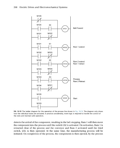
FIG. 10.19 The ladder diagram for the operation of the process line shown in Fig. 10.13. The diagram only shows
how the individual states are activated. In practice considerably, more logic is required to handle the control of
the rams and maintain safe operation.
detects the arrival of the component, resulting in the belt stopping. Ram 1 will then move
the component into the process until the switch LS2 is activated. On activation, Ram 1 is
retracted clear of the process and the conveyor and Ram 2 activated until the third
switch, LS3, is then operated. At the same time, the manufacturing process will be
initiated. On completion of the process, the components is then ejected, by the process