
Page 45 - Electric Drives and Electromechanical Systems
P. 45
38 Electric Drives and Electromechanical Systems
dynamic of both rotary and linear systems as applied to drive, motion profiles and
aspects related to the integration of a drive system into a full application. With the
increasing concerns regarding system safety in operation the risks presented to and by a
drive are considered, together with possible approaches to their mitigation.
2.1 Rotary systems
2.1.1 Fundamental relationships
In general, a motor drives a load through some form of transmission system in a drive
system and although the motor always rotates the load or loads may either rotate or
undergo a translational motion. The complete package will probably also include a
speed-changing system, such as a gearbox or belt drive. It is convenient to represent
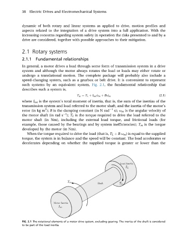
such systems by an equivalent system, Fig. 2.1, the fundamental relationship that
describes such a system is,
T m ¼ T L þ I tot _ u m þ B _ u m (2.1)
where I tot is the system’s total moment of inertia, that is, the sum of the inertias of the
transmission system and load referred to the motor shaft, and the inertia of the motor’s
2
rotor (in kg m ); B is the damping constant (in N rad 1 s); u m is the angular velocity of
1
the motor shaft (in rad s ); T L is the torque required to drive the load referred to the
motor shaft (in Nm), including the external load torque, and frictional loads (for
example, those caused by the bearings and by system inefficiencies); T m is the torque
developed by the motor (in Nm).
When the torque required to drive the load (that is, T L þ B u m ) is equal to the supplied
torque, the system is in balance and the speed will be constant. The load accelerates or
decelerates depending on whether the supplied torque is greater or lower than the
FIG. 2.1 The rotational elements of a motor drive system, excluding gearing. The inertia of the shaft is considered
to be part of the load inertia.