
Page 50 - Electric Drives and Electromechanical Systems
P. 50
Chapter 2 Analysing a drive system 43
3.1. The gear train also changes the inertia of the load as seen from the input to the gear
train, the reflected inertia is given by,
I L
I ref ¼ 2 (2.7)
n
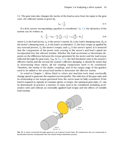
If a drive system incorporating a gearbox is considered, Fig. 2.4, the dynamics of the
system can be written as,
T L a L I L B L
T m ¼ T diff ¼ 2 þ I m þ u m 2 þ B m (2.8)
n n n n
where I L is the load inertia, I m is the motor’s inertia, B L is the load’s damping term, B m is
the motor’s damping term, a L is the load’s acceleration, T L the load torque as applied by
any external process, T m the motor’s torque, and u m is the motor’s speed. It is assumed
that the components of the power train rotating at the motor’s and load’s speed are
incorporated into the relevant inertias. Whether the load accelerates or decelerates de-
pends on the difference between the torque generated by the motor and the load torque
reflected through the gear train, T diff .In Eq. (2.8), the first bracketed term is the system’s
effective inertia and the second the system’s effective damping. It should be noted that
in determining these values, all the rotating components need to be considered.
Therefore, the inertia of the shafts, couplings, and of the output stage of the gearbox
need to be added to the actual load inertia to determine the effective inertia.
As noted in Chapter 1, drives fitted to robots and machine tools must continually
change speed to generate the required motion profile. The selection of the gear ratio and
its relationship to the torque generated from the motor must be fully considered. If the
load is required to operate at constant speed, or torque, the optimum gear ratio, n*, can
be determined. In practice, a number of cases need to be considered, including accel-
eration with and without an externally applied load torque and the effects of variable
load inertias.
FIG. 2.4 A motor connected through gearing to an external inertial load. All components that are accelerated or
decelerated must be incorporated into the overall torque estimation process.