
Page 46 - Electric Drives and Electromechanical Systems
P. 46
Chapter 2 Analysing a drive system 39
required driving torque. Therefore, during acceleration, the motor must supply not only
the output torque but also the torque which is required to accelerate the rotating system,
i.e., overcome the system inertia and frictional losses. In addition, when the angular
speed of the load changes, for example from u 1 to u 2 there is a corresponding change in
the system’s kinetic energy, E k , given by;
2 2
I tot u u 1
2
DE k ¼ (2.2)
2
where I tot is the total moment of inertia of the system that is subjected to the speed
change. The direction of the energy flow will depend on whether the load is being
accelerated or decelerated. If the application has a high inertia and if it is subjected to
rapid changes of speed, the energy flow in the drive must be considered in some detail,
since it will place restrictions on the size of the motor and its drive, particularly if excess
energy has to be dissipated, as discussed in Section 7.4.
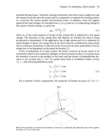
In the consideration of a rotary system, the body’s moment of inertia needs to be
considered, which is the rotational analogue of mass for linear motion. For a point mass
the moment of inertia is the product of the mass and the square of perpendicular dis-
2
tance to the rotation axis, I ¼ mr . If a point mass body is considered within a body,
Fig. 2.2, the following definitions hold:
Z
2 2
I xx ¼ y þ z dm
Z
2 2
I yy ¼ x þ z dm (2.3)
Z
2 2
I zz ¼ x þ y dm
For a number of basic components, the moments of inertia are given in Table 2.1.
FIG. 2.2 The approach to calculating the moment of inertia for a solid body, the elemental mass is dm, together
the values of r for all three axes.