
Page 49 - Electric Drives and Electromechanical Systems
P. 49
42 Electric Drives and Electromechanical Systems
From this table it is possible to calculate the moment of inertia around one axis, and
then compute the moment of inertia, I, around a second parallel axis, using the parallel
axis theorem, where,
I ¼ I G þ Md 2 (2.4)
and I G is the moment of inertia of the body, M is the mass of the body and d is the
distance between the new axis of rotation and the original axis of rotation.
2.1.2 Torque considerations
The torque which must be overcome in order to permit the load to be accelerated can be
considered to have the following components:
Friction torque, T f , results from relative motion between surfaces, and it is found in
bearings, lead screws, gearboxes, slideways, etc. A linear friction model that can be
applied to a any system is discussed in Section 2.5.
Windage torque, T w , is caused by the rotating components setting up air (or other
fluid) movement and is proportional to the square of the speed.
Load torque, T L , is determined by the application, the identification of which has
been discussed in part within Chapter 1. The load torque is also required to accel-
erate and decelerate the power train, which will be discussed in Chapter 2.
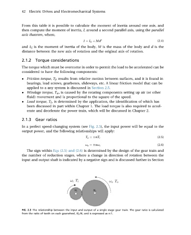
2.1.3 Gear ratios
In a perfect speed-changing system (see Fig. 2.3), the input power will be equal to the
output power, and the following relationships will apply:
(2.5)
T o ¼ nT i
(2.6)
u o ¼ nu i
The sign within Eqs (2.5) and (2.6) is determined by the design of the gear train and
the number of reduction stages, where a change in direction of rotation between the
input and output shaft is indicated by a negative sign and is discussed further in Section
FIG. 2.3 The relationship between the input and output of a single stage gear train. The gear ratio is calculated
from the ratio of teeth on each gearwheel, N 2 :N 1 and is expressed as n:1.