
Page 54 - Electric Drives and Electromechanical Systems
P. 54
Chapter 2 Analysing a drive system 47
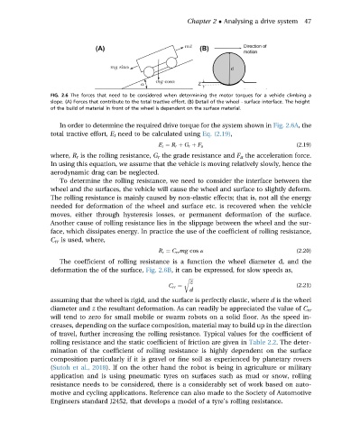
FIG. 2.6 The forces that need to be considered when determining the motor torques for a vehicle climbing a
slope. (A) Forces that contribute to the total tractive effort. (B) Detail of the wheel - surface interface. The height
of the build of material in front of the wheel is dependent on the surface material.
In order to determine the required drive torque for the system shown in Fig. 2.6A, the
total tractive effort, E t need to be calculated using Eq. (2.19),
E t ¼ R r þ G r þ F a (2.19)
where, R r is the rolling resistance, G r the grade resistance and F a the acceleration force.
In using this equation, we assume that the vehicle is moving relatively slowly, hence the
aerodynamic drag can be neglected.
To determine the rolling resistance, we need to consider the interface between the
wheel and the surfaces, the vehicle will cause the wheel and surface to slightly deform.
The rolling resistance is mainly caused by non-elastic effects; that is, not all the energy
needed for deformation of the wheel and surface etc. is recovered when the vehicle
moves, either through hysteresis losses, or permanent deformation of the surface.
Another cause of rolling resistance lies in the slippage between the wheel and the sur-
face, which dissipates energy. In practice the use of the coefficient of rolling resistance,
C rr is used, where,
R r ¼ C rr mg cos a (2.20)
The coefficient of rolling resistance is a function the wheel diameter d, and the
deformation the of the surface, Fig. 2.6B, it can be expressed, for slow speeds as,
r ffiffiffi
z
C rr ¼ (2.21)
d
assuming that the wheel is rigid, and the surface is perfectly elastic, where d is the wheel
diameter and z the resultant deformation. As can readily be appreciated the value of C rr
will tend to zero for small mobile or swarm robots on a solid floor. As the speed in-
creases, depending on the surface composition, material may to build up in the direction
of travel, further increasing the rolling resistance. Typical values for the coefficient of
rolling resistance and the static coefficient of friction are given in Table 2.2. The deter-
mination of the coefficient of rolling resistance is highly dependent on the surface
composition particularly if it is gravel or fine soil as experienced by planetary rovers
(Sutoh et al., 2018). If on the other hand the robot is being in agriculture or military
application and is using pneumatic tyres on surfaces such as mud or snow, rolling
resistance needs to be considered, there is a considerably set of work based on auto-
motive and cycling applications. Reference can also made to the Society of Automotive
Engineers standard J2452, that develops a model of a tyre’s rolling resistance.