
Page 56 - Electric Drives and Electromechanical Systems
P. 56
Chapter 2 Analysing a drive system 49
G r ¼ mg sin a ¼ 6:82 N
F a ¼ m € x ¼ 0:25 N
Hence the total attractive effort required is 8 N, if two wheels are driven, the torque
requirement per wheel is,
E t r
T d ¼ ¼ 0:4Nm
n d
If the maximum torque that can be applied before the wheel slips,
mgmr cos a
T d max ¼ ¼ 0:72 Nm
n t
As T d < T d max the mobile robot will be able to climb the slope.
nnn
2.4 Force based systems
Series Elastic Actuators are low speed, high force/mass, high power/mass actuators with
good force control as well as impact tolerance. In addition, they have low impedance and
friction, and thus can achieve high quality force control. For these reasons they are
widely incorporated in power legged robots (Pratt and Williamson, 1995; Robinson et al.,
1999).
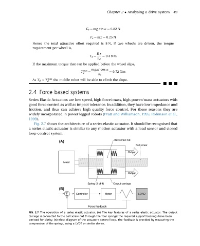
Fig. 2.7 shows the architecture of a series elastic actuator. It should be recognised that
a series elastic actuator is similar to any motion actuator with a load sensor and closed
loop control system.
FIG. 2.7 The operation of a series elastic actuator. (A) The key features of a series elastic actuator. The output
carriage is connected to the ball screw nut through the four springs; the required support bearings have been
omitted for clarity. (B) Block diagram of the actuator’s control loop. The feedback is provided by measuring the
compression of the springs, using a LVDT or similar device.