
Page 57 - Electric Drives and Electromechanical Systems
P. 57
50 Electric Drives and Electromechanical Systems
In practice the series elastic actuator consists of two subassemblies: a drive train
subassembly and an output carriage subassembly, Fig. 2.7A. When assembled,
the output carriage is coupled to the drive train through springs. During operation, the
servomotor directly drives the ball screw, which pushes on the compression springs that
transmit forces to the load. The force on the load is calculated by measuring the
compression of the springs using position transducers, such as a linear potentiometer or
linear variable differential transformer as discussed in Section 4.3.2.
The series elastic actuator uses active force sensing and closed loop control to reduce
friction and inertia, Fig. 2.7A. By measuring the compression of the compliant element,
the force on the load can be calculated using Hooke’s law. A feedback controller
calculates the error between the actual force and the desired force. The actuator’s design
introduces compliance between the actuator’s output and the load, allowing for greatly
increased control gains.
2.5 Friction
In the determination of the force required within a drive system it is important to
accurately determine the frictional forces this is of particular importance when a ma-
chine tool retro-fit or upgrade is being undertaken, where parameters may be difficult to
obtain, and the system has undergone significant amounts of wear and tear. Friction
occurs when two load-bearing surfaces are in relative motion. The fundamental source
of friction is easily appreciated when it is noted that even the smoothest surface consists
of microscopic peaks and troughs. Therefore, in practice, only a few points of contact
bear the actual load, leading to virtual welding, and hence a force is required to shear
these contact points. The force required to overcome the surface friction, F f , for a nor-
mally applied load, N, is given by the standard friction model,
F f ¼ mN (2.26)
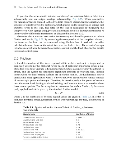
where m is the coefficient of friction; typical values are given in Table 2.3. In order to
minimise frictional forces, lubrication with or without bearings are used, as discussed in
Section 3.4.
Table 2.3 Typical values for the coefficient of friction, m, between
two materials.
Material pairs Coefficient of friction
Aluminium and Aluminium 1.05e1.35
Aluminium and Mild steel 0.61
Mild steel and Brass 0.51
Mild steel and Mild steel 0.74
Tool steel and Brass 0.24
Tool steel and PTFE 0.05e0.3
Tool steel and Stainless steel 0.53
Tool steel and Polyethylene 0.65
Tungsten carbide and Mild steel 0.4e0.6