
Page 60 - Electric Drives and Electromechanical Systems
P. 60
Chapter 2 Analysing a drive system 53
machine tool is generated by the controller, on the basis of knowledge of the pro-
file required and the size of the cutter. The cutter has to follow a path that will
produce the required profile; this requires careful design of the profile to ensure
that the cutter will not have to follow corners or radii that would be physically
impossible to cut.
The trajectory described in Fig. 2.9C are defined in terms of the machine’s coordinate
frame, the actual trajectories of the individual joint axes have to be generated at run
time, the rate at which the profile is generated is termed the path-update rate, and for a
typical system lies between 60 and 2000 Hz, using the inverse kinematic approach as
discussed in Section 1.3.1.
In many cases it is necessary to specify the motion in considerable detail, a
commonly used approach is to give the trajectory as a sequence of via or intermediate
points. To complete the motion the tool (or more correctly in the case of a robots, the
tool frame) has to pass through these points with a specific velocity. In order to prevent
undesired rapid speed or acceleration changes, that could cause damage to the power
train, a degree of blending or smoothing should be used (Craig, 2005).
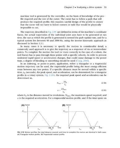
In an indexing, or point-to-point, application, either a triangular or a trapezoidal
motion trajectory can be used, the trapezoidal profile being the most energy-efficient
route between any two points. If a specific distance must be moved within a specific
time, t m (seconds), the peak speed, and acceleration, can be determined; for a triangular
profile in a rotary system, Fig. 2.10A, the required peak speed and acceleration can be
determined as,
2q m
N max ¼ (2.30)
t m
2N max
a ¼ (2.31)
t m
where q m is the distance moved in revolutions, N max , the maximum speed required, and
a is the required acceleration. For a trapezoidal motion profile, and if the time spent on
FIG. 2.10 Motion profiles, the total distance covered, and time to complete the motion are identical in both cases.
(A) Triangular motion profile. (B) Trapezoidal motion profile.