
Page 59 - Electric Drives and Electromechanical Systems
P. 59
52 Electric Drives and Electromechanical Systems
2.6 Motion trajectories
The motion trajectory refers to the position velocity and acceleration as a function of
time for each degree of freedom. As opposed to a motion path, that is used to refer to
move where the positional points (normally the start and finish points), are specified, but
the time for the move or together with any intermediary point are not specified. One
significant problem is how to specify the problem - the user does not want to write down
a detailed function, but rather specify a simple description of the move required.
Examples of this approach include:
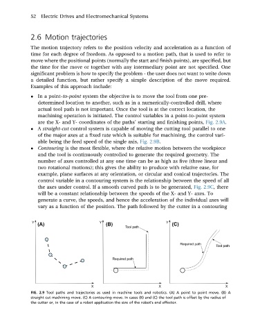
In a point-to-point system the objective is to move the tool from one pre-
determined location to another, such as in a numerically-controlled drill, where
actual tool path is not important. Once the tool is at the correct location, the
machining operation is initiated. The control variables in a point-to-point system
are the X- and Y- coordinates of the paths’ starting and finishing points, Fig. 2.9A.
A straight-cut control system is capable of moving the cutting tool parallel to one
of the major axes at a fixed rate which is suitable for machining, the control vari-
able being the feed speed of the single axis, Fig. 2.9B.
Contouring is the most flexible, where the relative motion between the workpiece
and the tool is continuously controlled to generate the required geometry. The
number of axes controlled at any one time can be as high as five (three linear and
two rotational motions); this gives the ability to produce with relative ease, for
example, plane surfaces at any orientation, or circular and conical trajectories. The
control variable in a contouring system is the relationship between the speed of all
the axes under control. If a smooth curved path is to be generated, Fig. 2.9C, there
will be a constant relationship between the speeds of the X- and Y- axes. To
generate a curve, the speeds, and hence the acceleration of the individual axes will
vary as a function of the position. The path followed by the cutter in a contouring
FIG. 2.9 Tool paths and trajectories as used in machine tools and robotics. (A) A point to point move. (B) A
straight cut machining move. (C) A contouring move. In cases (B) and (C) the tool path is offset by the radius of
the cutter or, in the case of a robot application the size of the robot's end effector.