
Page 176 - Electrical Equipment Handbook _ Troubleshooting and Maintenance
P. 176
POWER ELECTRONICS, RECTIFIERS, AND PULSE-WIDTH MODULATION INVERTERS
POWER ELECTRONICS, RECTIFIERS, AND INVERTERS 9.3
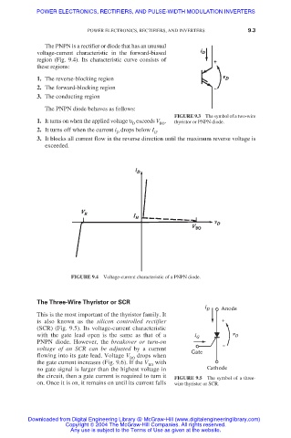
The PNPN is a rectifier or diode that has an unusual
voltage-current characteristic in the forward-biased
region (Fig. 9.4). Its characteristic curve consists of
these regions:
1. The reverse-blocking region
2. The forward-blocking region
3. The conducting region
The PNPN diode behaves as follows:
FIGURE 9.3 The symbol of a two-wire
1. It turns on when the applied voltage υ exceeds V . thyristor or PNPN diode.
D
BO
2. It turns off when the current i drops below I .
D H
3. It blocks all current flow in the reverse direction until the maximum reverse voltage is
exceeded.
FIGURE 9.4 Voltage-current characteristic of a PNPN diode.
The Three-Wire Thyristor or SCR
This is the most important of the thyristor family. It
is also known as the silicon controlled rectifier
(SCR) (Fig. 9.5). Its voltage-current characteristic
with the gate lead open is the same as that of a
PNPN diode. However, the breakover or turn-on
voltage of an SCR can be adjusted by a current
flowing into its gate lead. Voltage V BO drops when
the gate current increases (Fig. 9.6). If the V with
BO
no gate signal is larger than the highest voltage in
the circuit, then a gate current is required to turn it FIGURE 9.5 The symbol of a three-
on. Once it is on, it remains on until its current falls wire thyristor or SCR.
Downloaded from Digital Engineering Library @ McGraw-Hill (www.digitalengineeringlibrary.com)
Copyright © 2004 The McGraw-Hill Companies. All rights reserved.
Any use is subject to the Terms of Use as given at the website.