
Page 181 - Electrical Equipment Handbook _ Troubleshooting and Maintenance
P. 181
POWER ELECTRONICS, RECTIFIERS, AND PULSE-WIDTH MODULATION INVERTERS
9.8 CHAPTER NINE
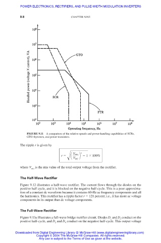
FIGURE 9.11 A comparison of the relative speeds and power-handling capabilities of SCRs,
GTO thyristors, and power transistors.
The ripple r is given by
2
V rms
r 1 100%
V
DC
where V rms is the rms value of the total output voltage from the rectifier.
The Half-Wave Rectifier
Figure 9.12 illustrates a half-wave rectifier. The current flows through the diodes on the
positive half cycle, and it is blocked on the negative half-cycle. This is a poor approxima-
tion of a constant dc waveform because it contains 60-Hz ac frequency components and all
the harmonics. This rectifier has a ripple factor r 121 percent; i.e., it has more ac voltage
components in its output than dc voltage components.
The Full-Wave Rectifier
Figure 9.13a illustrates a full-wave bridge rectifier circuit. Diodes D and D conduct on the
1
3
positive half-cycle, and D and D conduct on the negative half-cycle. This output voltage
4
2
Downloaded from Digital Engineering Library @ McGraw-Hill (www.digitalengineeringlibrary.com)
Copyright © 2004 The McGraw-Hill Companies. All rights reserved.
Any use is subject to the Terms of Use as given at the website.