
Page 178 - Electrical Equipment Handbook _ Troubleshooting and Maintenance
P. 178
POWER ELECTRONICS, RECTIFIERS, AND PULSE-WIDTH MODULATION INVERTERS
POWER ELECTRONICS, RECTIFIERS, AND INVERTERS 9.5
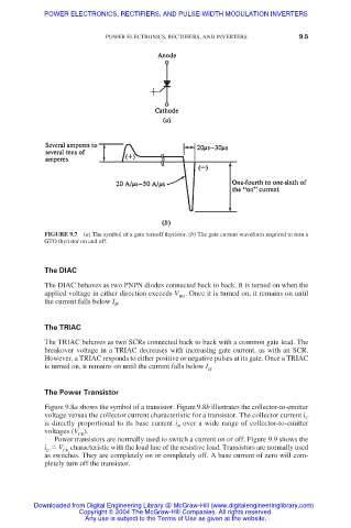
FIGURE 9.7 (a) The symbol of a gate turnoff thyristor. (b) The gate current waveform required to turn a
GTO thyristor on and off.
The DIAC
The DIAC behaves as two PNPN diodes connected back to back. It is turned on when the
applied voltage in either direction exceeds V . Once it is turned on, it remains on until
BO
the current falls below I .
H
The TRIAC
The TRIAC behaves as two SCRs connected back to back with a common gate lead. The
breakover voltage in a TRIAC decreases with increasing gate current, as with an SCR.
However, a TRIAC responds to either positive or negative pulses at its gate. Once a TRIAC
is turned on, it remains on until the current falls below I .
H
The Power Transistor
Figure 9.8a shows the symbol of a transistor. Figure 9.8b illustrates the collector-to-emitter
voltage versus the collector current characteristic for a transistor. The collector current i
C
is directly proportional to its base current i over a wide range of collector-to-emitter
B
voltages (V ).
CE
Power transistors are normally used to switch a current on or off. Figure 9.9 shows the
i V characteristic with the load line of the resistive load. Transistors are normally used
C
CE
as switches. They are completely on or completely off. A base current of zero will com-
pletely turn off the transistor.
Downloaded from Digital Engineering Library @ McGraw-Hill (www.digitalengineeringlibrary.com)
Copyright © 2004 The McGraw-Hill Companies. All rights reserved.
Any use is subject to the Terms of Use as given at the website.