
Page 180 - Electrical Equipment Handbook _ Troubleshooting and Maintenance
P. 180
POWER ELECTRONICS, RECTIFIERS, AND PULSE-WIDTH MODULATION INVERTERS
POWER ELECTRONICS, RECTIFIERS, AND INVERTERS 9.7
The Insulated Gate Bipolar Transistor (IGBT)
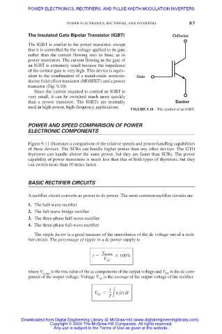
The IGBT is similar to the power transistor, except
that it is controlled by the voltage applied to its gate
rather than the current flowing into its base, as in
power transistors. The current flowing in the gate of
an IGBT is extremely small because the impedance
of the control gate is very high. This device is equiv-
alent to the combination of a metal-oxide semicon-
ductor field effect transistor (MOSFET) and a power
transistor (Fig. 9.10).
Since the current required to control an IGBT is
very small, it can be switched much more quickly
than a power transistor. The IGBTs are normally
used in high-power, high-frequency applications.
FIGURE 9.10 The symbol of an IGBT.
POWER AND SPEED COMPARISON OF POWER
ELECTRONIC COMPONENTS
Figure 9.11 illustrates a comparison of the relative speeds and power-handling capabilities
of these devices. The SCRs can handle higher power than any other devices. The GTO
thyristors can handle almost the same power, but they are faster than SCRs. The power
capability of power transistors is much less than that of both types of thyristors, but they
can switch more than 10 times faster.
BASIC RECTIFIER CIRCUITS
A rectifier circuit converts ac power to dc power. The most common rectifier circuits are
1. The half-wave rectifier
2. The full-wave bridge rectifier
3. The three-phase half-wave rectifier
4. The three-phase full-wave rectifier
The ripple factor is a good measure of the smoothness of the dc voltage out of a recti-
fier circuit. The percentage of ripple in a dc power supply is
V ac,rms
r 100%
V
DC
where V ac,rms is the rms value of the ac components of the output voltage and V DC is the dc com-
ponent of the output voltage. Voltage V DC is the average of the output voltage of the rectifier
1
V DC υ (t) dt
o
T
Downloaded from Digital Engineering Library @ McGraw-Hill (www.digitalengineeringlibrary.com)
Copyright © 2004 The McGraw-Hill Companies. All rights reserved.
Any use is subject to the Terms of Use as given at the website.