
Page 185 - Electrical Equipment Handbook _ Troubleshooting and Maintenance
P. 185
POWER ELECTRONICS, RECTIFIERS, AND PULSE-WIDTH MODULATION INVERTERS
9.12 CHAPTER NINE
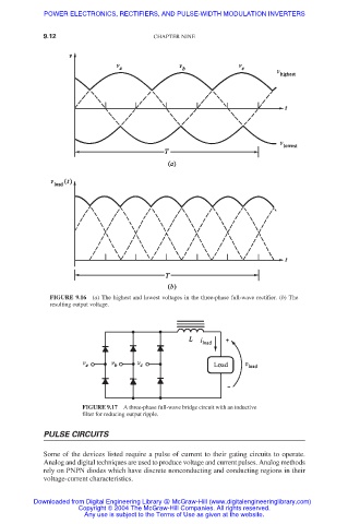
FIGURE 9.16 (a) The highest and lowest voltages in the three-phase full-wave rectifier. (b) The
resulting output voltage.
FIGURE 9.17 A three-phase full-wave bridge circuit with an inductive
filter for reducing output ripple.
PULSE CIRCUITS
Some of the devices listed require a pulse of current to their gating circuits to operate.
Analog and digital techniques are used to produce voltage and current pulses. Analog methods
rely on PNPN diodes which have discrete nonconducting and conducting regions in their
voltage-current characteristics.
Downloaded from Digital Engineering Library @ McGraw-Hill (www.digitalengineeringlibrary.com)
Copyright © 2004 The McGraw-Hill Companies. All rights reserved.
Any use is subject to the Terms of Use as given at the website.