
Page 187 - Electrical Equipment Handbook _ Troubleshooting and Maintenance
P. 187
POWER ELECTRONICS, RECTIFIERS, AND PULSE-WIDTH MODULATION INVERTERS
9.14 CHAPTER NINE
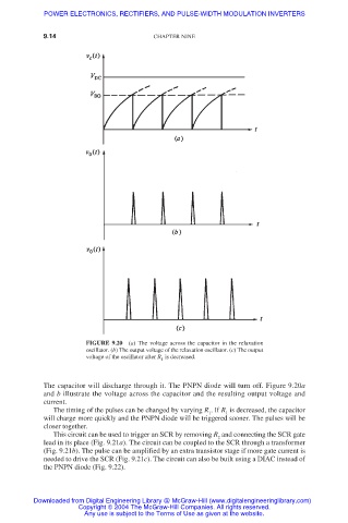
FIGURE 9.20 (a) The voltage across the capacitor in the relaxation
oscillator. (b) The output voltage of the relaxation oscillator. (c) The output
voltage of the oscillator after R is decreased.
1
The capacitor will discharge through it. The PNPN diode will turn off. Figure 9.20a
and b illustrate the voltage across the capacitor and the resulting output voltage and
current.
The timing of the pulses can be changed by varying R . If R is decreased, the capacitor
1
1
will charge more quickly and the PNPN diode will be triggered sooner. The pulses will be
closer together.
This circuit can be used to trigger an SCR by removing R and connecting the SCR gate
2
lead in its place (Fig. 9.21a). The circuit can be coupled to the SCR through a transformer
(Fig. 9.21b). The pulse can be amplified by an extra transistor stage if more gate current is
needed to drive the SCR (Fig. 9.21c). The circuit can also be built using a DIAC instead of
the PNPN diode (Fig. 9.22).
Downloaded from Digital Engineering Library @ McGraw-Hill (www.digitalengineeringlibrary.com)
Copyright © 2004 The McGraw-Hill Companies. All rights reserved.
Any use is subject to the Terms of Use as given at the website.