
Page 192 - Electrical Equipment Handbook _ Troubleshooting and Maintenance
P. 192
POWER ELECTRONICS, RECTIFIERS, AND PULSE-WIDTH MODULATION INVERTERS
POWER ELECTRONICS, RECTIFIERS, AND INVERTERS 9.19
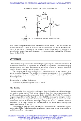
FIGURE 9.28 An ac phase angle controller using a DIAC and
a TRIAC.
load cannot change instantaneously. This means that the current to the load will not rise
immediately upon firing the SCR and will not stop flowing at exactly the end of the half-
cycle. At the end of the half-cycle, the inductive voltage on the load will keep the SCR
turned on for a short time, until the current flowing through the load and the SCR drops
below I (Fig. 9.29).
H
INVERTERS
The static frequency conversion is the most rapidly growing area in modern electronics. It
involves the conversion of ac power at one frequency to ac power at another frequency by
using solid-state electronics. The traditional approaches to static ac frequency conversion
employ the cycloconverter and the rectifier-inverter.
The cycloconverter is a device that directly converts ac power at one frequency to ac
power at another frequency. The rectifier-inverter converts ac power to dc power and then
converts dc power to ac power at a different frequency. A rectifier-inverter is divided into
two components:
1. A rectifier to produce the dc power
2. An inverter to produce ac power from dc power
The Rectifier
The basic rectifier described earlier used diodes. These devices have a problem when they
are used for motor control. Their output voltage is fixed for a given input voltage. This
problem can be overcome by replacing the diodes with SCRs (Fig. 9.30). The average dc
output voltage of this rectifier depends on when the SCRs are triggered during the positive
half-cycle. If they are triggered at the beginning of the half-cycle, this circuit will be the
same as the rectifier with diodes. The output voltage will be 0 V if the SCRs are never
triggered. The dc output voltage will be between 0 V and the maximum for any other
firing angle between 0° and 180°.
The output voltage of this circuit will have more harmonic content than a simple rectifier
due to using SCRs. An inductor and a capacitor are placed at the output of the rectifier to
assist in smoothing the dc output.
Downloaded from Digital Engineering Library @ McGraw-Hill (www.digitalengineeringlibrary.com)
Copyright © 2004 The McGraw-Hill Companies. All rights reserved.
Any use is subject to the Terms of Use as given at the website.