
Page 194 - Electrical Equipment Handbook _ Troubleshooting and Maintenance
P. 194
POWER ELECTRONICS, RECTIFIERS, AND PULSE-WIDTH MODULATION INVERTERS
POWER ELECTRONICS, RECTIFIERS, AND INVERTERS 9.21
FIGURE 9.30 A three-phase rectifier circuit using SCRs to provide control of
the dc output voltage level.
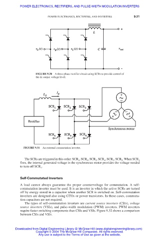
FIGURE 9.31 An external commutation inverter.
The SCRs are triggered in this order: SCR , SCR , SCR , SCR , SCR , SCR . When SCR
1 6 2 4 3 5 1
fires, the internal generated voltage in the synchronous motor provides the voltage needed
to turn off SCR .
3
Self-Commutated Inverters
A load cannot always guarantee the proper countervoltage for commutation. A self-
commutation inverter must be used. It is an inverter in which the active SCRs are turned
off by energy stored in a capacitor when another SCR is switched on. Self-commutation
inverters are designed also using GTOs or power transistors. In these cases, commuta-
tion capacitors are not required.
The types of self-commutation inverters are current source inverters (CSIs), voltage
source inverters (VSIs), and pulse-width modulation (PWM) inverters. PWM inverters
require faster switching components than CSIs and VSIs. Figure 9.32 shows a comparison
between CSIs and VSIs.
Downloaded from Digital Engineering Library @ McGraw-Hill (www.digitalengineeringlibrary.com)
Copyright © 2004 The McGraw-Hill Companies. All rights reserved.
Any use is subject to the Terms of Use as given at the website.