
Page 195 - Electrical Equipment Handbook _ Troubleshooting and Maintenance
P. 195
POWER ELECTRONICS, RECTIFIERS, AND PULSE-WIDTH MODULATION INVERTERS
9.22 CHAPTER NINE
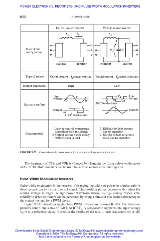
FIGURE 9.32 Comparison of current source inverters and voltage source inverters.
The frequency of CSIs and VSIs is changed by changing the firing pulses on the gates
of the SCRs. Both inverters can be used to drive ac motors at variable speeds.
Pulse-Width Modulation Inverters
Pulse-width modulation is the process of changing the width of pulses in a pulse train in
direct proportion to a small control signal. The resulting pulses become wider when the
control voltage is larger. A high-power waveform whose average voltage varies sinu-
soidally to drive ac motors can be generated by using a sinusoid at a desired frequency as
the control voltage for a PWM circuit.
Figure 9.33 illustrates a single-phase PWM inverter circuit using IGBTs. The two com-
parators control the states of IGBT to IGBT . A comparator compares the input voltage
1 4
υ (t) to a reference signal. Based on the results of the test, it turns transistors on or off.
in
Downloaded from Digital Engineering Library @ McGraw-Hill (www.digitalengineeringlibrary.com)
Copyright © 2004 The McGraw-Hill Companies. All rights reserved.
Any use is subject to the Terms of Use as given at the website.