
Page 197 - Electrical Equipment Handbook _ Troubleshooting and Maintenance
P. 197
POWER ELECTRONICS, RECTIFIERS, AND PULSE-WIDTH MODULATION INVERTERS
9.24 CHAPTER NINE
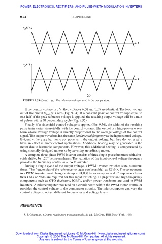
FIGURE 9.33 (Cont.)(c) The reference voltages used in the comparators.
If the control voltage is 0 V, then voltages υ (t) and υ (t) are identical. The load voltage
v
u
out of the circuit υ (t) is zero (Fig. 9.34). If a constant positive control voltage equal to
load
one-half of the peak reference voltage is applied, the resulting output voltage will be a train
of pulses with a 50 percent duty cycle (Fig. 9.35).
Finally, if a sinusoidal control voltage is applied (Fig. 9.36), the width of the resulting
pulse train varies sinusoidally with the control voltage. The output is a high-power wave-
form whose average voltage is directly proportional to the average voltage of the control
signal. The output waveform has the same fundamental frequency as the input control voltage.
Evidently, there are harmonic components in the output voltage, but they do not usually
have an effect in motor control applications. Additional heating may be generated in the
motor due to harmonic components. However, this additional heating is compensated by
using specially designed motors or by derating an ordinary motor.
A complete three-phase PWM inverter consists of three single-phase inverters with sinu-
soids shifted by 120° between phases. The variation of the input control voltage frequency
provides the frequency control in a PWM inverter.
During a single cycle of the output voltage, a PWM inverter switches state numerous
times. The frequencies of the reference voltages can be as high as 12 kHz. The components
in a PWM inverter must change state up to 24,000 times every second. Components faster
than CSIs or VSIs are required for this rapid switching. High-power and high-frequency
components such as GTO thyristors, IGBTs, and/or power transistors are used in PWM
inverters. A microcomputer mounted on a circuit board within the PWM motor controller
provides the control voltage to the comparator circuits. The microcomputer can vary the
control voltage to obtain different frequencies and voltage levels.
REFERENCE
1. S. J. Chapman, Electric Machinery Fundamentals, 2d ed., McGraw-Hill, New York, 1991.
Downloaded from Digital Engineering Library @ McGraw-Hill (www.digitalengineeringlibrary.com)
Copyright © 2004 The McGraw-Hill Companies. All rights reserved.
Any use is subject to the Terms of Use as given at the website.