
Page 198 - Electrical Equipment Handbook _ Troubleshooting and Maintenance
P. 198
POWER ELECTRONICS, RECTIFIERS, AND PULSE-WIDTH MODULATION INVERTERS
POWER ELECTRONICS, RECTIFIERS, AND INVERTERS 9.25
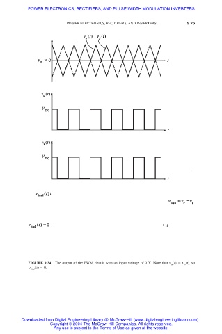
FIGURE 9.34 The output of the PWM circuit with an input voltage of 0 V. Note that υ (t) υ (t), so
v
u
υ load (t) 0.
Downloaded from Digital Engineering Library @ McGraw-Hill (www.digitalengineeringlibrary.com)
Copyright © 2004 The McGraw-Hill Companies. All rights reserved.
Any use is subject to the Terms of Use as given at the website.