
Page 203 - Electrical Equipment Handbook _ Troubleshooting and Maintenance
P. 203
VARIABLE-SPEED DRIVES
10.2 CHAPTER TEN
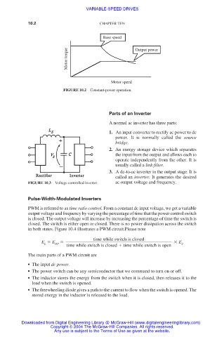
Base speed
Motor torque Output power
Motor speed
FIGURE 10.2 Constant-power operation.
Parts of an Inverter
A normal ac inverter has three parts:
1. An input converter to rectify ac power to dc
power. It is normally called the source
bridge.
2. An energy storage device which separates
the input from the output and allows each to
operate independently from the other. It is
usually called a link filter.
3. A dc-to-ac inverter in the output stage. It is
called an inverter. It generates the desired
FIGURE 10.3 Voltage controlled inverter. ac output voltage and frequency.
Pulse-Width-Modulated Inverters
PWM is referred to as time ratio control. From a constant dc input voltage, we get a variable
output voltage and frequency by varying the percentage of time that the power control switch
is closed. The output voltage will increase by increasing the percentage of time the switch is
closed. The switch is either open or closed. There is no power dissipation across the switch
in both states. Figure 10.4 illustrates a PWM circuit.Please note
time while switch is closed
E E E
L DF time while switch is closed time while switch is open d
The main parts of a PWM circuit are
● The input dc power.
● The power switch can be any semiconductor that we command to turn on or off.
● The inductor stores the energy from the switch when it is closed, then releases it to the
load when the switch is opened.
● The freewheeling diode gives a path to the current to flow when the switch is opened. The
stored energy in the inductor is released to the load.
Downloaded from Digital Engineering Library @ McGraw-Hill (www.digitalengineeringlibrary.com)
Copyright © 2004 The McGraw-Hill Companies. All rights reserved.
Any use is subject to the Terms of Use as given at the website.