
Page 204 - Electrical Equipment Handbook _ Troubleshooting and Maintenance
P. 204
VARIABLE-SPEED DRIVES
VARIABLE-SPEED DRIVES 10.3
i d
S 1
dc
Source L
Voltage F
E d
e i L R e
D F DF L L
(a)
t S , closed
E = E = 1 E
DF
L
t S , closed + t S , open d
1 1
e DF
t
(b)
e L
or
i L (c)
i d
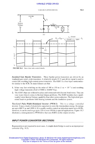
FIGURE 10.4 Basic time ratio control details.
Insulated Gate Bipolar Transistors. These bipolar power transistors are driven by an
insulated gate metal-oxide transistor. A relatively simple 15-V gate driver signal is used to
control the resulting high-current power transistor. The IGBT is a four-layer semiconduc-
tor similar to the SCR. Its main features are that
1. It has very fast switching on the order of 100 to 150 ns (1 ns 10 9 s) and resulting
high-voltage transients dυ/dt of 5000 to 10,000 V/ s.
2. The IGBT chips are soldered in place and connected with discrete bond wires. They are
very weak when it comes to thermal fatigue problems. The IGBT modules have signif-
icantly lower thermal fatigue capability than other semiconductors. The high dυ/dt gen-
erated leads to problems with bearing currents and the insulation system.
Two-Level Pulse-Width-Modulated Inverter (PWM-2). This is a voltage controlled
inverter. It uses a bank of electrolytic capacitors to store the intermediate energy. Its ratings
are up to 600 V ac and 1800 A. It is usually used to control an induction motor up to 60 Hz.
However, it can be used to go up to 120 or even 150 Hz in special applications. Figure 10.3
illustrates a nonregenerative PWM drive that uses IGBTs in the output inverter.
INPUT POWER CONVERTER (RECTIFIER)
Regeneration is not required in most cases. A simple diode bridge is used as an input power
converter (Fig. 10.5).
Downloaded from Digital Engineering Library @ McGraw-Hill (www.digitalengineeringlibrary.com)
Copyright © 2004 The McGraw-Hill Companies. All rights reserved.
Any use is subject to the Terms of Use as given at the website.