
Page 205 - Electrical Equipment Handbook _ Troubleshooting and Maintenance
P. 205
VARIABLE-SPEED DRIVES
10.4 CHAPTER TEN
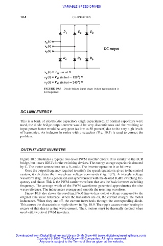
FIGURE 10.5 Diode bridge input stage (when regeneration is
not required).
DC LINK ENERGY
This is a bank of electrolytic capacitors (high-capacitance). If normal capacitors were
used, the diode bridge output current would be very discontinuous and the resulting ac
input power factor would be very poor (as low as 50 percent) due to the very high levels
of harmonics. An inductor in series with a capacitor (Fig. 10.3) is used to correct the
problem.
OUTPUT IGBT INVERTER
Figure 10.6 illustrates a typical two-level PWM inverter circuit. It is similar to the SCR
bridge, but it uses IGBTs for the switching devices. The energy storage capacitor is denoted
by C. The motor connections are a, b, and c. The inverter operation is as follows:
Once the output frequency required to satisfy the speed regulator is given to the control
system, it calculates the three-phase voltage commands (Fig. 10.7). A triangle voltage
waveform (Fig. 10.8) is generated and synchronized with the desired IGBT switching fre-
quency and phase. This is the PWM carrier waveform that sets the basic inverter switching
frequency. The average width of the PWM waveforms generated approximates the sine
wave reference. The inductances average and smooth the resulting waveform.
Figure 10.8 also shows the resulting PWM line-to-line output voltage compared to the
original sine wave reference. When the transistors are on, the current charges the motor
inductance. When they are off, the current freewheels through the corresponding diode.
This causes the characteristic ripple shown in Fig. 10.9. The ripple causes motor heating in
excess of that due to a sine wave current. Thus, motors must be thermally derated when
used with two-level PWM inverters.
Downloaded from Digital Engineering Library @ McGraw-Hill (www.digitalengineeringlibrary.com)
Copyright © 2004 The McGraw-Hill Companies. All rights reserved.
Any use is subject to the Terms of Use as given at the website.