
Page 209 - Electrical Equipment Handbook _ Troubleshooting and Maintenance
P. 209
VARIABLE-SPEED DRIVES
10.8 CHAPTER TEN
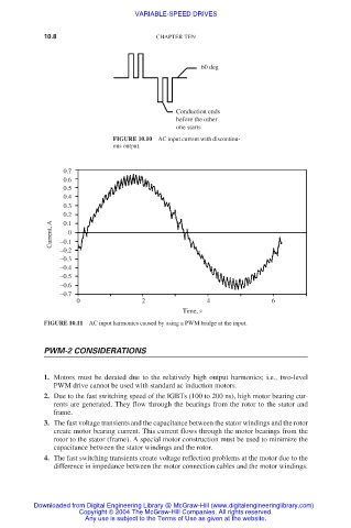
60 deg
Conduction ends
before the other
one starts
FIGURE 10.10 AC input current with discontinu-
ous output.
0.7
0.6
0.5
0.4
0.3
0.2
Current, A –0.1 0
0.1
–0.2
–0.3
–0.4
–0.5
–0.6
–0.7
0 2 4 6
Time, s
FIGURE 10.11 AC input harmonics caused by using a PWM bridge at the input.
PWM-2 CONSIDERATIONS
1. Motors must be derated due to the relatively high output harmonics; i.e., two-level
PWM drive cannot be used with standard ac induction motors.
2. Due to the fast switching speed of the IGBTs (100 to 200 ns), high motor bearing cur-
rents are generated. They flow through the bearings from the rotor to the stator and
frame.
3. The fast voltage transients and the capacitance between the stator windings and the rotor
create motor bearing current. This current flows through the motor bearings from the
rotor to the stator (frame). A special motor construction must be used to minimize the
capacitance between the stator windings and the rotor.
4. The fast switching transients create voltage reflection problems at the motor due to the
difference in impedance between the motor connection cables and the motor windings.
Downloaded from Digital Engineering Library @ McGraw-Hill (www.digitalengineeringlibrary.com)
Copyright © 2004 The McGraw-Hill Companies. All rights reserved.
Any use is subject to the Terms of Use as given at the website.